2. Description of AMON
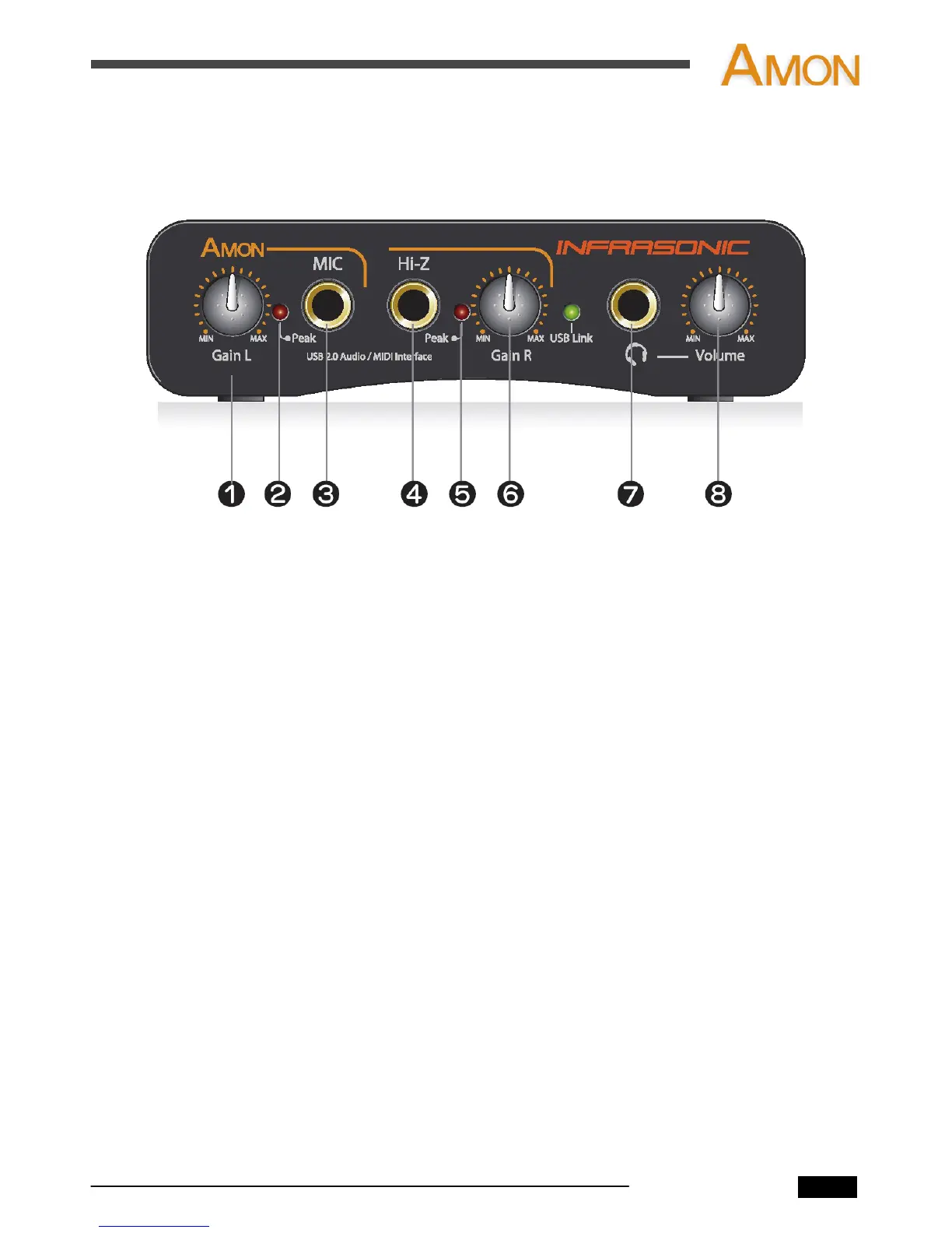
2.1 Front Panel
1. Microphone / Left Line Input Gain Control
- This knob adjusts the left side of the line input and microphone input gain.
2. Microphone Peak LED
- This LED light when the input signal is within -6dB of analog clipping.
If the peak LED flickers occasionally, the signal is approaching clipping levels,
but does not necessarily indicate distortion or actual clipping.
3. Microphone Input (1/4” TRS)
- Connect a dynamic microphone to this balanced 1/4” connector.
- Only dynamic microphones are available for this input. (no phantom power)
4. Hi-Z input (1/4” TS)
- Connect electric guitar or bass guitar to this unbalanced 1/4” connector.
- Only unbalanced 1/4” phone jack connection are available for Hi-Z input.
5. Hi-Z input Peak LED
- This LED light when the input signal is within -6dB of analog clipping.
If the peak LED flickers occasionally, the signal is approaching clipping levels,
but does not necessarily indicate distortion or actual clipping.
6. Hi-Z / Right Line Input Gain Control
- This knob adjusts the right Line and Hi-Z Input gain.
7. Headphone Output
- The high powered headphone output accommodates stereo headphones
with a 1/4” stereo plug.
8. Headphone Level
- This knob controls the overall output level of Headphone output.
AMON User’s Manual
2