IDS404 INSTALLER MANUAL NO. 700-277-02A ISSUED SEPT 2004 VER 1.02 11
IDS404 INSTALLER MANUAL
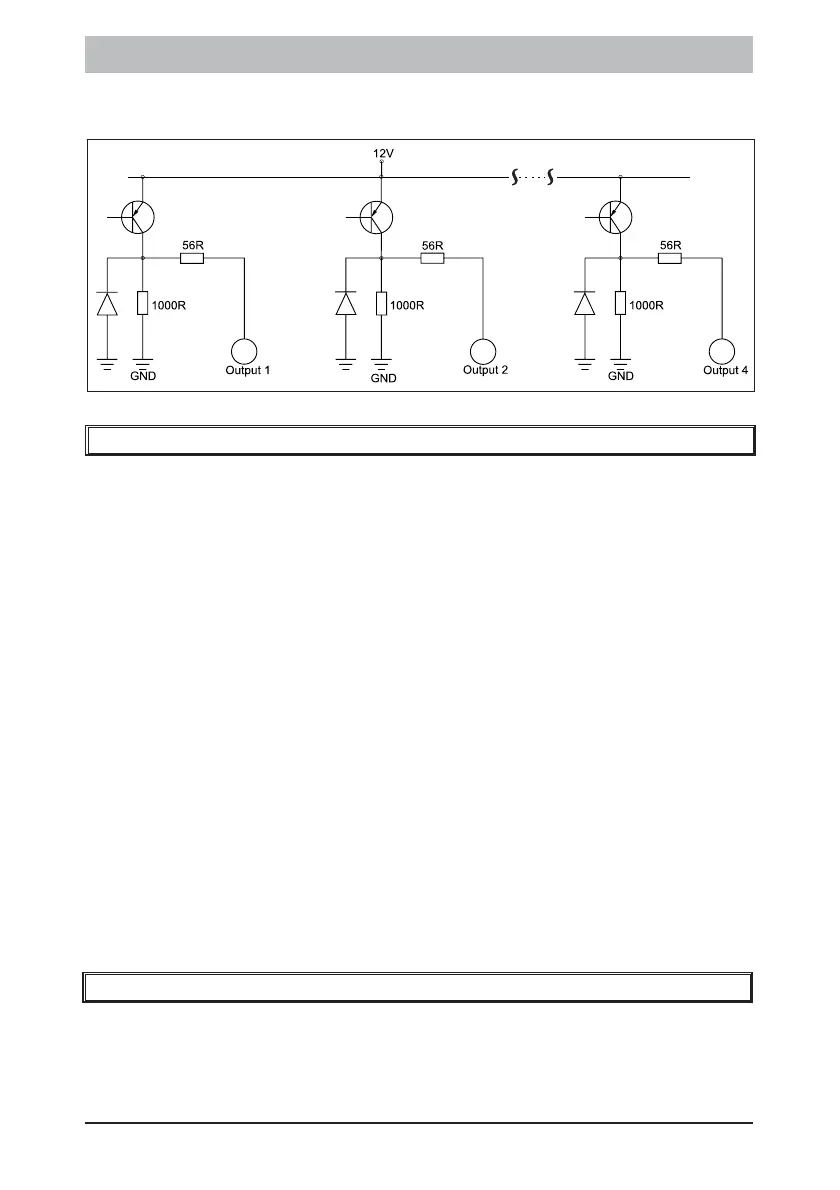
Figure 5: Programmable Output Configuration
9. The Key-Switch or Remote Control Unit
A momentary key-switch or non-latching remote control receiver may
be connected to any zone to allow remote arm/disarm capability and/
or remote panic.
! If a key-switch or remote control unit is used, a 3K3 resistor must
be connected between the zone input and ground. (Use the 4K7
and 12K resistors if tamper per zone is enabled).
! Use a normally open, spring-loaded momentary key-switch or a
non-latching remote control unit. The remote receiver must
provide a pulsed output.
! If using a key-switch, program the zone as an Arm/Disarm zone
i.e. a value of [5] entered into the relevant location.
! If using a remote control, program the zone as either a Paniczone
or an Arm/Disarm zone, as required.
! The panel will arm instantly (no entry/exit delay) when arming by
means of a key-switch or remote control unit.
! The panel has an exit delay which can be enabled or disabled
with the key-switch or remote control (See location 12).
10. Additional Technical Data
! Use a suitable transformer with an output voltage of between 15
volts and 18V with a minimum rating of 16VA. A 32 VA
transformer is preferable for larger installations.