IDS800 INSTALLER MANUAL NO. 700-175-02N ISSUED JUL 2003 VER 1.45 9
IDS800 INSTALLER MANUAL
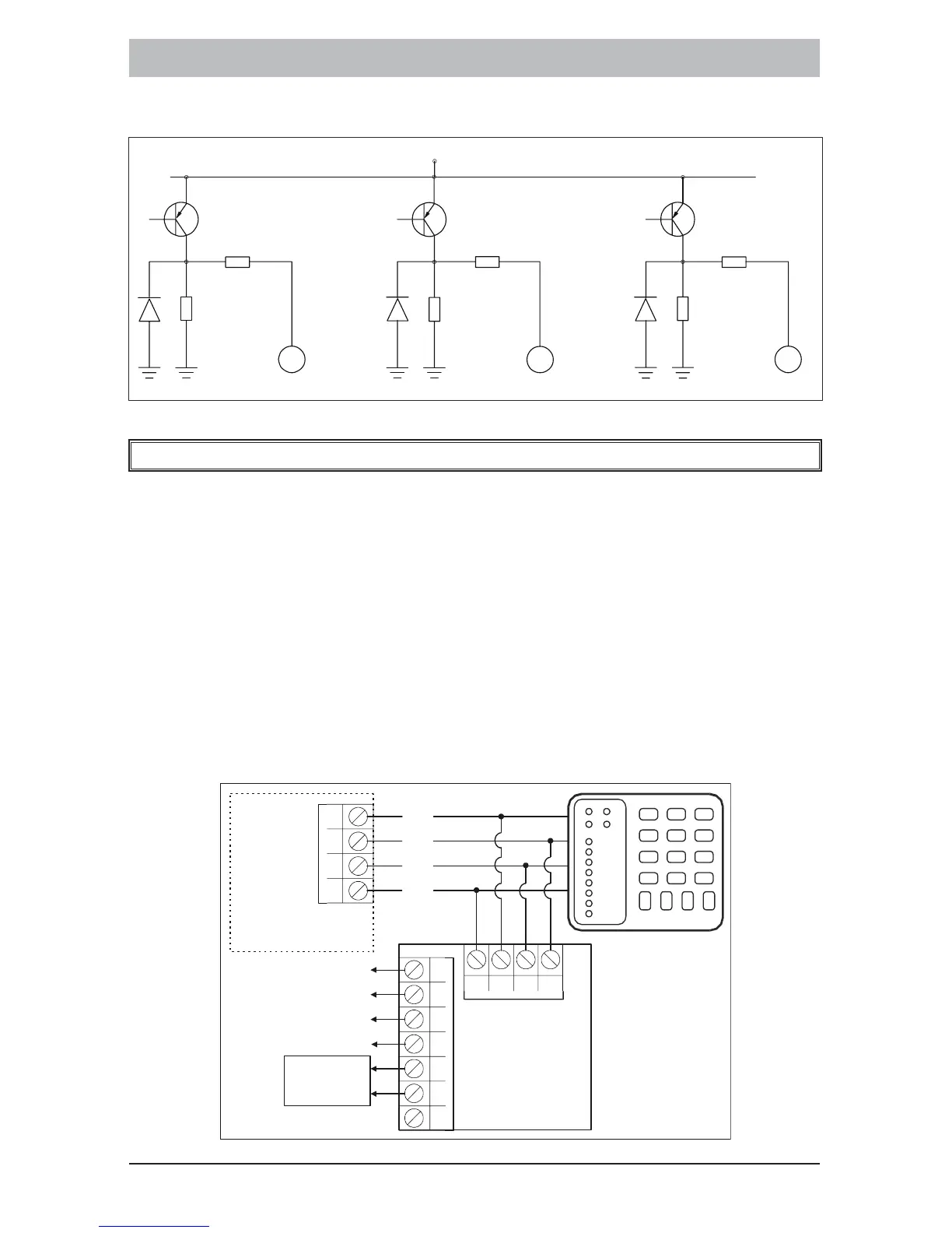
Figure 4: Programmable Output Configuration
6. Expansion Board
Attached to the keypad bus, in parallel with the keypad, is an optional
expansion board which allows for the following:
Programmable outputs 4 and 5 which function as per the values
programmed into locations 22 - 40 and locations 159 - 166.
Designated keypad buzzer which will function as per the
description in the user manual.
ARM, READY and POWER LED’s which will function as per the
description in the user manual for keypad LEDs.
Figure 5: Expansion Board Connection
Keypad
123
4
56
789
0
*
#
P
M
O
D
E
ZONE 1
ZONE 2
ZONE 3
ZONE 4
ZONE 5
ZONE 6
ZONE 7
ZONE 8
GND
CK
DAT
+12V
+
C
D
_
Keypad connection
on main board
+
GD
DT
CK
BZ
PR
RD
AM
P4
P5
GD
Keypad Buzzer
Power LED
Ready LED
Arm LED
Auxilliary
Outputs
Expansion
Board
FM
12V
56R
1000R
GND
Output 2
56R
1000R
GND
Output 1
56R
1000R
GND
Output
 Loading...