22 User Interface
Installation and programming manual
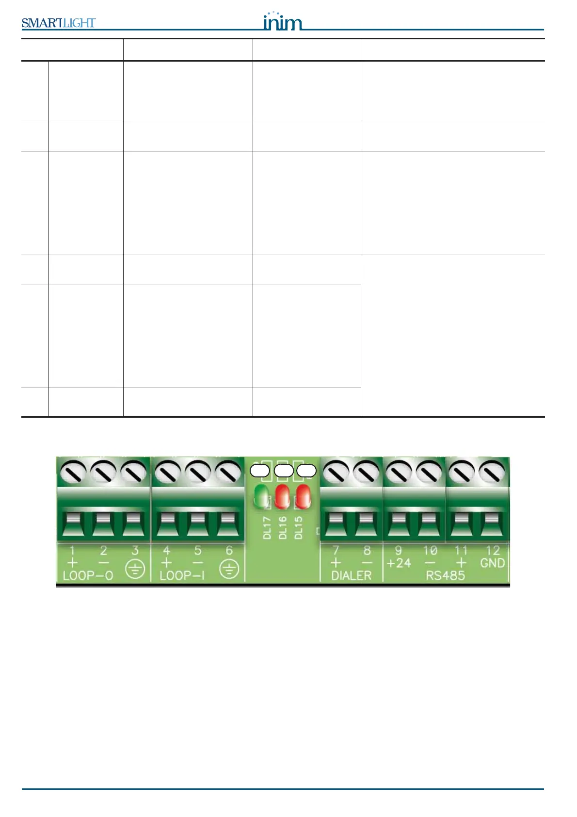
5.2 Internal LEDs
Figure 7 - Internal LEDs
These LEDs indicate communication between the panel and the detectors. They indicate that the panel is
interrogating its devices, the protocol it is using and whether or not the interrogated devices have responded.
• The green LED [A] (nearest to the Loop-I terminals) will blink each time a loop device responds during
the interrogation phase of the devices from address 1 through to the maximum number of devices
allowed (refer to Appendix A, Appendix B and Appendix C regarding the number of devices
accommodated by the loop).
• The red LED [B] will blink each time a command is sent to a loop device using Enea (Appendix A) or
Argus (Appendix B).
• The red LED [C] on the far right will blink each time a command is sent to a loop device using Apollo
(Appendix C) communication protocol.
[Z] DISABLE
MANUAL
Indicates disablement of
manual extinguish
commands, via the
appropriate key (paragraph
5.1 - [I]).
[A1] EXTINGUISH Indicates that fire
extinction is running.
[B1] PRE-
EXTINGUISH
Indicates activation of the
pre-extinguish output;
refer to paragraph 6.8 -
Connecting the
extinguishant module
(optional), terminal PRE-
EXT.
Indicates that only
one zone is in alarm
status, therefore, the
extinguishant system
will not be activated. If
another zone latches
in alarm, the
extinguishant system
will be activated.
[C1] FAULT Indicates trouble with the
fire extinction circuits.
Indicates restoral of a
fault event.
This condition can be cleared by reset
only (level 2).
[D1
]
STOP
EXTINGUISH
Indicates that the fire
extinguishant system has
been stopped from a
remote hold-off unit; refer
to paragraph 6.8 -
Connecting the
extinguishant module
(optional), terminal STOP-
EXT.
Indicates restoral of a
Stop extinguishant
event.
[E1] CPU FAULT Indicates a CPU fault that
requires immediate repair.
Indicates restoral of a
fault event.
LED ON Solid: Blinking: Note
A B C