2 Wiring
2
- 17 -
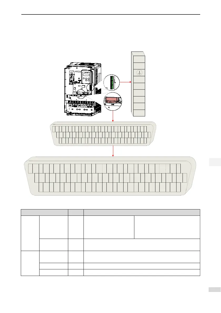
2.3.2 Control Signal Terminal Connector CN1
Figure 2-7 Pin layout of control circuit terminal connector of servo drive
DO4+
DO3-
GND
DO3+
DO2-
DO2+
DO1-
DO1+
DI4
DI1
DI2
COM+
DI9
COM-
+5V
OCA
GND
OCB
PAO+
PAO-
PBO-
PZO-
PBO+
DO4-
DO5-
GND
DI8
DI7
DI6
DI5
DI3
PULLHI
HPULSE-
SIGN+
HPULSE+
SIGN-
HSIGN-
PULSE+
HSIGN+
PULSE-
PZ
-
OUT
PZO+
DO5+
+24V
1
16
31
15
30
44
CN1
1
2
16
3
4
5
6
7
8
9
10
11
12
14
15
18
19
20
21
22
23
24
25
26
27
29
30
31
32
33
34
35
36
37
38
39
40
41
42
43
44
13
28
17
CN1
AI1
AI2
GND
PTC
AI3
GND
AO
/
PTC
CN6 CN7 CN8
Table 2-2 Pulse position reference input signals
Signal Pin No. Function Description
Position
reference
PULSE+
PULSE-
SIGN+
SIGN-
41
43
37
39
Low-speed pulse input mode
Differential drive mode
OC mode
Pulse input format:
Direction + Pulse
Phase A + B quadrature pulse
CW/CCW pulse
HPULSE+
HPULSE-
38
36
High-speed reference pulse input
Position
reference
HSIGN+
HSIGN-
42
40
High-speed position reference symbols
PULLHI 35 External power input terminal of reference pulse
GND 29 Signal ground

 Loading...