MD380 User Manual Mechanical and Electrical Installation
- 39 -
–
Do not connect the earthing terminal to the neutral conductor of the power supply.
–
The impedance of the PE conductor must be able to withstand the large short-
circuit current that may arise when a fault occurs.
–
Select the size of the PE conductor according to the following table:
Cross-sectional Area of a
Phase Conductor (S)
Min. Cross-sectional Area of
Protective Conductor (Sp)
S ≤ 16 mm
2
S
16 mm
2
< S ≤ 35 mm
2
16 mm
2
35 mm
2
< S S/2
–
You must use a yellow/green cable as the PE conductor.
7) Requirements on upstream protection device
–
Install upstream protection device on the input power circuit. The protection device
must provide the protections on overcurrent, short-circuit and electrical solation.
–
When selecting the protective device, you should consider the current capacity
of the power cable, system overload capacity and short-circuit capacity of
the upstream power distribution of the equipment. Generally, make selection
according to the recommended values in section 8.4.
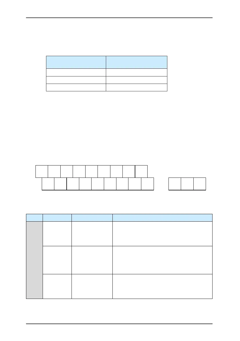
3.2.3 Description of Control Circuit Terminals
■
Terminal Arrangement of Control Circuit
+24V
+10V AI1 AI2 DI1 DI2 DI3 DI4 DI5 COM
GND GND AO1 CME COM DO1 FM OP T/A T/B T/C
■
Description of Control Circuit Terminals
Table 3-3 Description of the use of control circuit terminals
Type Terminal Name Function Description
Power supply
+10V-GND
External +10 V
power supply
Provide +10 V power supply to external unit.
Generally, it provides power supply to external
potentiometer with resistance range of 1–5 kΩ.
Maximum output current: 10 mA
+24V-COM
External +24
V power
supplyApplying
to Overvoltage
Category II circuit
Provide +24 V power supply to external unit.
Generally, it provides power supply to DI/DO
terminals and external sensors.
Maximum output current: 200 mA
OP
Input terminal of
external power
supply
Connect to +24 V by default.
When DI1-DI5 need to be driven by external
signal, OP needs to be connected to external
power supply and be disconnected from +24 V.

 Loading...
