Mechanical and Electrical Installation MD380 User Manual
- 40 -
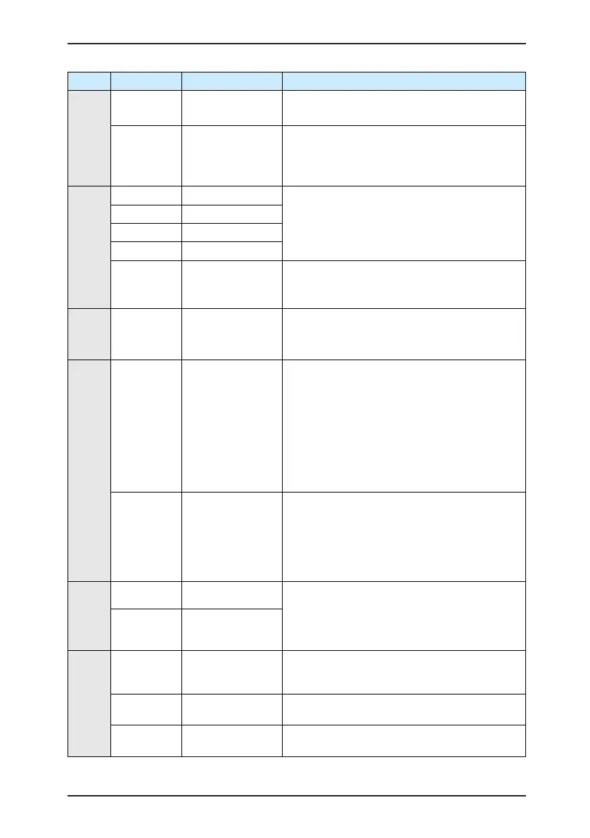
Type Terminal Name Function Description
Analog input
AI1-GND Analog input 1
Input voltage range: 0–10 V
Resistance input: 100 kΩ
AI2-GND Analog input 2
Input range: 0–10 V/4–20 mA, decided by jumper
J8 on the control board
Resistance input: 22 kΩ (voltage input), 500 Ω
(current input)
Digital input
DI1- OP Digital input 1
Optical coupling isolation, compatible with dual
polarity input
Resistance input: 2.4 kΩ
Voltage range for level input: 9–30 V
DI2- OP Digital input 2
DI3- OP Digital input 3
DI4- OP Digital input 4
DI5- OP
High-speed pulse
input
Besides features of DI1–DI4, it can be used for
high-speed pulse input.
Maximum input frequency: 100 kHz
Analog
output
AO1-GND Analog output 1
Voltage or current output is decided by jumper J5.
Output voltage range: 0–10 V
Output current range: 0–20 mA
Digital output
DO1-CME Digital output 1
Optical coupling isolation, dual polarity open
collector output
Output voltage range: 0–24 V
Output current range: 0–50 mA
Note that CME and COM are internally insulated,
but they are shorted by jumper externally. In this
case DO1 is driven by +24 V by default. If you
want to drive DO1 by external power supply,
remove the jumper.
FM- COM
High-speed pulse
output
It is limited by F5-00 (FM terminal output mode
selection).
As high-speed pulse output, the maximum
frequency hits 100 kHz.
As open-collector output, its specication is the
same as that of DO1
Relay output
T/A-T/B NC terminal
Contact driving capacity:
250 VAC, 3 A, COSø = 0.4
30 VDC, 1 A
Applying to Overvoltage Category II circuit
T/A-T/C NO terminal
Auxiliary interface
J12
Extension card
interface
Interface of 28-core terminal and optional cards
(I/O extension card, PLC card and various bus
cards)
J3 PG card interface
OC, differential, UVW and resolver can be
selected.
J7
External operation
panel interface
Connect to external operation panel.

 Loading...
