MD380 User Manual Mechanical and Electrical Installation
- 41 -
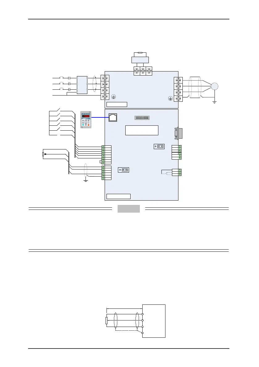
3.2.4 Wiring of AC Drive Control Circuit
Figure 3-14 Wiring mode of the AC drive control circuit
250 VAC, 10 mA to 3A
30 VDC, 10 mA to 1 A
Fault contact output
Interface for
external
operation
panel
PG card interface
Extension card
interface
MD380
R
S
T
M
(+)
(-) PB
U
V
W
MF.K
RUN
STOP
RES
QUICK
PRG ENTER
RUN
LOCAL/REMOT FED/REV TUNE/TC
RPM
%
A VHz
J7
10V
AI1
AI2
PE
COM
GND
AO1
DO1
GND
COM
OP
24V
T/A1
T/B1
T/C1
Fault output
(NC/NO)
Three-phase
AC power
L2
L3
L1
PE
MCCB
MC
Contactor
Circular
magnetic core
(wind a coil)
L2
L3
L1
PE
S
T
R
Filter
MDBUN
Braking unit
Braking resistor
Shielded
cable
Main circuit
Control circuit
Jumper
bar
DI1
DI2
DI3
DI4
1
–
5 kΩ
1
2
3
Shielded
cable
Forward RUN
Forward JOG
Fault reset
Multi-reference
terminal 1
Multi-reference
terminal 2
CME
DI5
J8
I V
AI2 voltage/current
selection
J5
I V
AO1 voltage/current
selection
FM
COM
J3
J12
Circuit
breaker
• All MD380 series AC drives have the same wiring mode. The gure here shows the wiring of
single-phase 220 VAC drive. ◎ indicates main circuit terminal, while ○ indicates control circuit
terminal.
• When the external operation panel is connected, the display of the operation panel on the
MD380 goes off.
■
Description of Wiring of Signal Terminals
1) Wiring of AI terminals
Weak analog voltage signals are easy to suffer external interference, and therefore the
shielded cable must be used and the cable length must be less than 20 m, as shown in
following gure.
Figure 3-15 Wiring mode of AI terminals
+10 V
AI1
GND
P
o
t
e
n
t
i
o
m
e
t
e
r
PE
< 20 m
MD380

 Loading...
