Mechanical and Electrical Installation MD380 User Manual
- 42 -
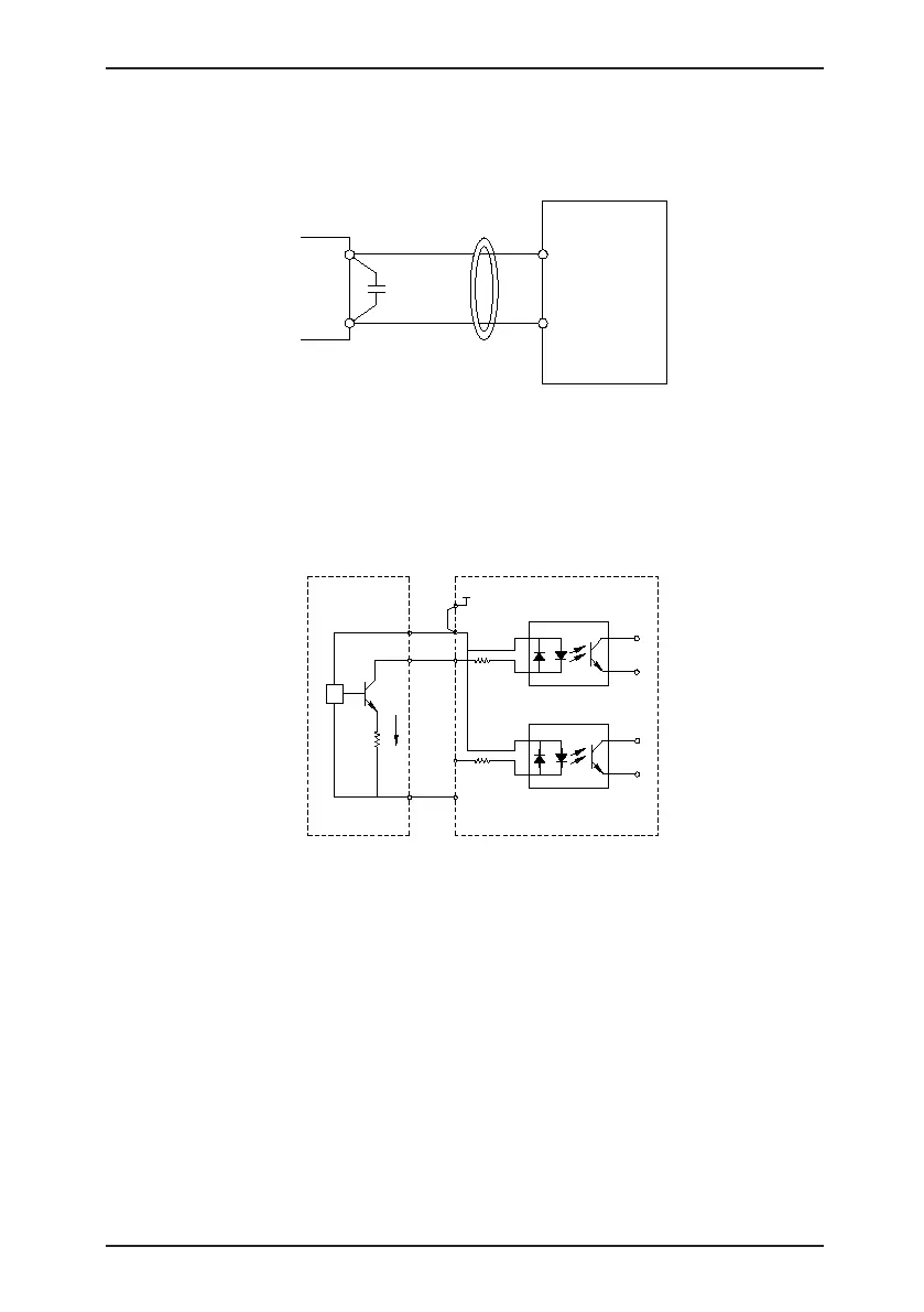
In applications where the analog signal suffers severe interference, install filter
capacitor or ferrite magnetic core at the analog signal source.
Figure 3-16 Install lter capacitor or ferrite magnetic core
AI1
GND
Cross or wind two or three
coils in the same direction
0.022 uF, 50 V
Ferrite
magnetic core
C
MD380
2) Wiring of DI terminals
Generally, select shielded cable no longer than 20 m. When active driving is adopted,
necessary ltering measures shall be taken to prevent the interference to the power
supply. It is recommended to use the contact control mode.
a. SINK wiring
Figure 3-17 Wiring in SINK mode
0V
DI5
DI1
OP
+24V
+24V
2.4k
2.4k
3.3Ω
NPN
Signal
External
controller
Control board
of the AC drive
+VCC
COM
This is the most commonly used wiring mode. To apply external power supply, remove
jumpers between +24 V and OP and between COM and CME, and connect the positive
pole of external power supply to OP and negative pole to CME.
In such wiring mode, the DI terminals of different AC drives cannot be connected in
parallel. Otherwise, DI mal-function may result. If parallel connection (different AC
drives) is required, connect a diode in series at the DI and the diode needs to satisfy
the requirement: IF > 10 mA, UF < 1 V.

 Loading...
