MD380 User Manual Mechanical and Electrical Installation
- 43 -
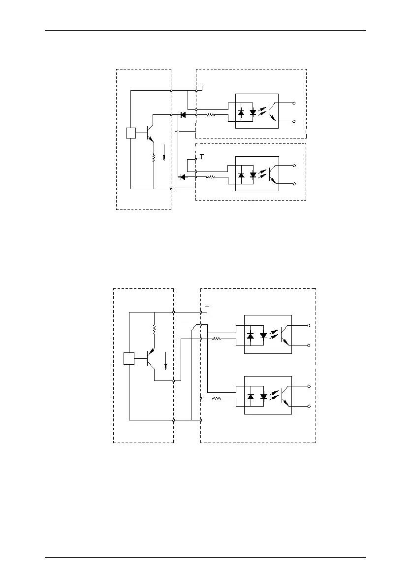
Figure 3-18 DI terminals connected in parallel in SINK mode
0V
DI1
OP
+24V
+24V
2.4k
3.3Ω
NPN
Signal
External
controller
Control board
of AC drive 2
+VCC
COM
DI1
OP
+24V
2.4k
Control board
of AC drive 1
COM
b. SOURCE wiring
In such wiring mode, remove the jumper between +24 V and OP. Connect +24 V to
the common port of external controller and meanwhile connect OP to COM. If external
power supply is applied, remove the jumper between CME and COM.
Figure 3-19 Wiring in SOURCE mode
0V
DI5
DI1
OP
+24V
+24V
2.4k
2.4k
3.3Ω
PNP
Signal
External
controller
Control board of
the AC drive
+VCC
COM

 Loading...
