MD380 User Manual Operation, Display and Application Example
- 61 -
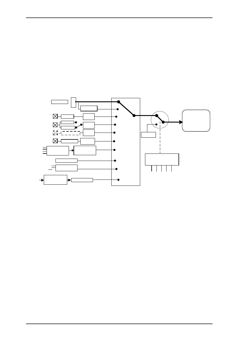
According to the preceding figure, the running frequency of the AC drive can be set by
means of function codes, manual adjustment, analog input, multi-speed terminal, external
feedback signal, internal PID regulator, or the host computer.
Set the corresponding function codes of each frequency setting mode, as shown in the
preceding gure.
4.8.2 Frequency Setting by the Auxiliary Frequency Source
The frequency setting by the auxiliary frequency source is the same as the frequency setting
by the main frequency source. You can set the auxiliary frequency source in F0-04.
Figure 4-18 Frequency set by the auxiliary frequency source
F0-04
(Auxiliary
frequency
source Y
)
0
0-10 V
1
▲
▼
Retentive at
power failure
0-10 V
4-20 mA
JP8
F0-08
-10 V to 10 V
AI1
AI2
AI3
On the
extension
board
F4-04=30
DI5
Pulse
setting
2
3
4
5
F4-00 to F4-09
= 12/13/14/15
Multi-speed
6
Analog
Analog
DI1-DI10
FC-00 to FC-15
(each
frequency)
Group FC
Simple PLC
Group FA
PID
H1000 register
Communication
setting
Host
computer
7
8
9
AI1-AI2
F4-33
F4-33
F4-33
F4-29
to F4-32
Analog
FD-00 to FD-05
Communication
configuration
DI5 (f )
Digital setting
Auxiliary
frequency
source Y
F4-00 to F4-09
= 40
DI1 to DI10
Frequency
switchover
F0-08
The relationship between the target running frequency and the main frequency source and
auxiliary frequency source is set in F0-07, as follows:
1) Main frequency source X: The main frequency source is directly used to set the target
running frequency.
2) Auxiliary frequency source Y: The auxiliary frequency source is directly used to set the
target running frequency.
3) X and Y operation: There are four operation methods, namely, X+Y, X-Y, maximum of X
and Y, and minimum of X and Y.
4) Frequency switchover: A DI terminal is used to switch over between the preceding
three frequency setting channels.

 Loading...
