Operation, Display and Application Examples
MD380 User Manual
- 62 -
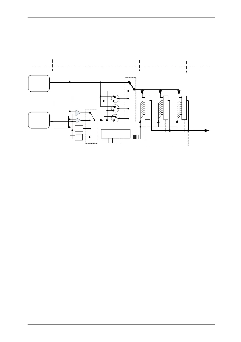
The following figure shows how to set the relationship in F0-07, in which the bold line
indicates the default setting.
Figure 4-19 Relationship between the target running frequency and main and auxiliary
frequency sources
Auxiliary
source Y
F0-05
F0-06
F0-07
(unit's digit)
Target running
frequency
Main
frequency
source X
+
--
Max
Min
0
1
2
3
0
1
2
3
4
F0-07
(ten's digit)
F4-00 to F4-09
= 18
DI1 to DI10
Frequency
switchover
X
Y
XY
F0-27 (default value: 000)
Hundred's digit Ten's digit Unit's digit
(Communication) (Terminal) (Operation panel)
0
1
2
3
4
5
6
7
8
9
0
1
2
3
4
5
6
7
8
9
0
1
2
3
4
5
6
7
8
9
2 1 0
F0-02 (Command
source selection)
9 frequency
setting
channels
Frequency
source
selection
Frequency source
operation
Frequency source
switchover
Binding command
source to frequency
source
Target running
frequency
Amplitude
limit
The operation between the main frequency source and the auxiliary frequency source can
be used for closed-loop speed control. For example, using the main frequency source for
setting the required frequency and the auxiliary frequency source for automatic adjustment,
in conjunction with switchover performed by the external DI terminal signal, the required
closed-loop control can be implemented.
4.8.3 Binding Command Source to Frequency Source
The three command sources can be separately bound to frequency sources, as shown in
Figure 4-19. When the specied command source (F0-02) is bound to a frequency source
(corresponding digit in the value of F0-27), the frequency is determined by the frequency
setting channel set in F0-27. In this case, both main and auxiliary frequency sources are
ineffective.

 Loading...
