MD380 User Manual Operation, Display and Application Example
- 63 -
4.8.4 AI as the Frequency Source
The AI terminal can be used as the frequency source. The MD380 provides two AI terminals
(AI1 and AI2) on the control board, and the optional I/O extension card provides another AI
terminal (AI3).
The following gures show how to use the AI as the frequency source.
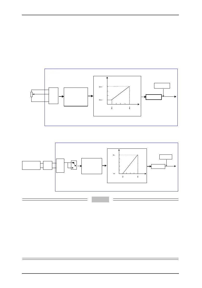
Figure 4-20 Voltage input of AI1 connected to the potentiometer as the frequency source
(2–10 V corresponding to 10–40 Hz)
F4-13 = 0.00 V
F4-14 = 0.0%
F4-15 = 10.00 V
F4-16 = 100%
F4-17 = 0.1s
F0-03 = 2
Running
frequency
Terminal
Function code
(default value)
10V
AI1
.
GND
Frequency
source selection
F0-07 = 0
Analog setting
Frequency
feature setting
F4-13 to F4-17: relationship between
AI1 setting and corresponding value
1
2
3
0-10 VDC
Potentiometer
2 kΩ
Default:
0-10 V corresponding to 0-50 Hz
F4-33: AI curve selection
AI
Corresponding
setting
80.0
60.0
40.0
20.0
0.0
0
2.00 4.00 6.00 8.00 10.00
F4-13
F4-14
F4-16
F4-15
2-10 V corresponding to 10-40 Hz
F0-10 = 50.00 Hz
F4-33 = 1
0.0
Unit: V
Unit: %
Figure 4-21 Current input of AI2 connected to 4DA module of the PLC as the frequency
source (4–20 mA corresponding to 0–50 Hz)
F0-03 = 2
Running
frequency
Terminal
Function code
(default value)
Frequency
source selection
F0-07=0
Frequency
feature setting
F4-18 to F4-22: relationship between AI1
setting and corresponding value
Default:
0-10 V corresponding to
0-50 Hz
F4-33: AI curve selection
F4-18 = 0.00 V
F4-19 = 0.0%
F4-20 = 10.00 V
F4-21 = 100%
F4-22 = 0.1s
AI
20.0
F4-18
F4-19
F4-20
4-20 mA corresponding to 0-50 Hz
F0-10 = 50.00 Hz
16.012.08.0
4.0
F4-33 = 10
100.
0
F4-21
0
80.0
60.0
40.0
20.0
0.0
Corresponding
setting
Unit: mA
Unit: %
V
I
Selection
using jumper
J8
AI2
GND
Analog setting
Selection using
jumper J8
I: AI2 current input
V: AI2 voltage input
PLC
4D/A module
AO
GND
Note: Select the analog input type
based on the output type of the
D/A module.
1. MD380 provides two AI terminals (AI1 and AI2) on the control board, and the optional I/O
extension card provides another AI terminal (AI3).
2. AI1 provides 0–10 V voltage input. AI2 provides 0–10 V voltage input or 4–20 mA current input,
determined by jumper J8 on the control board. AI3 provides -10 V to +10 V bipolar voltage input.
3. When AI is used as the frequency source, 100% of the voltage or current input corresponding
setting corresponds to the maximum frequency in F0-10.
4. When the temperature transmitter is used for analog setting, it must be connected to AI3 on the
I/O extension card.
5. MD380 provides ve corresponding relationship curves, which can be selected in F4-33. The
input values and corresponding settings of each curve are set in F4-13 to F4-27 and group A6.

 Loading...
