Operation, Display and Application Examples
MD380 User Manual
- 64 -
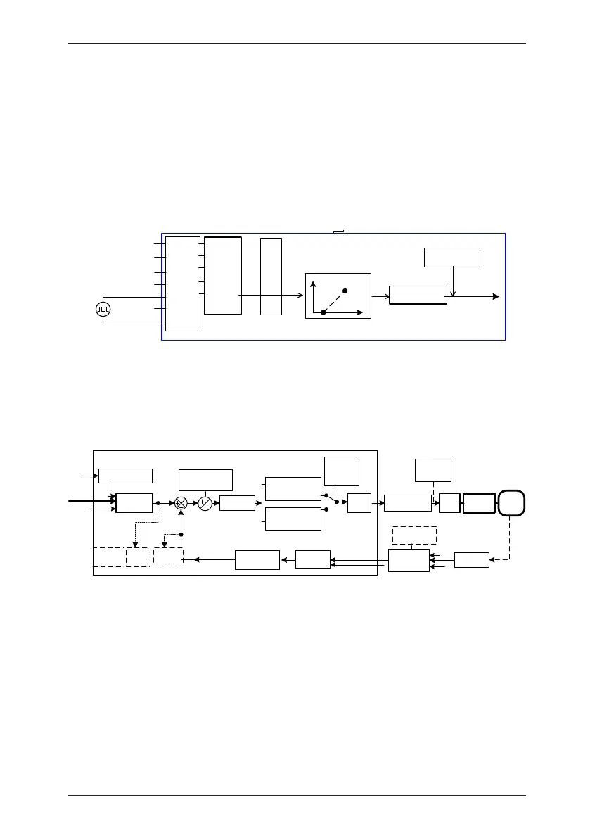
4.8.5 Pulse Setting as the Frequency Source
In many scenarios, pulse input is used as the frequency source. The specications of pulse
signals are: voltage 9–30 V, frequency 0–100 kHz.
Only DI5 can be used for pulse input. The relationship between pulse input from DI5 and
the corresponding setting is set in F4-28 to F4-31. The relationship is a two-point line, and
100% of pulse input corresponding setting corresponds to the maximum frequency of F0-10,
as shown in Figure 4-22.
Figure 4-22 Pulse setting as the frequency source
F4-00
F4-01
F4-02
F4-03
F4-04
.
.
.
.
.
30
.
F0-03 = 5
Running
frequency
Terminal
Function
code
Setting
value
DI1
DI2
DI3
DI4
DI5
.
COM
Frequency
source selection
OC output
F0-07 = 0
Pulse setting
Frequency
feature setting
F4-28 to F4-31:
Relationship between
pulse setting frequency
and running frequency
*
Only DI5 can be used for pulse input.
4.8.6 Frequency Closed-Loop Control
The MD380 has a built-in PID regulator. Together with the frequency sources, the PID
regulator can implement automatic adjustment of progress control, such as constant
temperature, constant pressure, and tension control.
Figure 4-23 Automatic adjustment by PID regulator
F0-07 = 0
F0-27 = 0
F0-03 = 8
Frequency
source selection
FA-00
(PID setting
source
)
Setting
target
Built-in PID
regulator
FA-01
(PID digital setting)
FA-03 (PID action
direction)
0: Forward action
1: Reverse action
FA-09
(
PID deviation
limit)
FA-04
(PID setting
feedback
range
)
PID1:
Proportional Kp
1: FA-05
Integral Ti1: FA-06
Derivative Td1: FA-07
PID2:
Proportional Kp2: FA-15
Integral Ti
2: FA-16
Derivative Td2: FA-17
FA-13
FA-23
FA-24
PWM
drive
Execution
by motor
Object
FA-18
FA-19
FA
-20
Switchover
condition
Transmitter
detection
FA-12
(PID feedback
filter time)
FA-02 (PID
feedback
source)
PID
feedback
PID output
feature
PID output
frequency
U0-15
(PID
setting )
U0-16
(PID
feedback)
PID
setting
F4-33
AI parameter
feature
preprocessing
F4-13 to F4-32
(Calibration
curve)
Physical
quantity
Electric
signal
%
%
%
When PID frequency closed-loop control is implemented, F0-03 (Main frequency source X
selection) must be set to 8 (PID). The PID-related parameters are set in group FA, as shown
in Figure 4-23.
The MD380 has two built-in equivalent PID calculating units. You can set the features,
such as adjustment speed and accuracy, for the two units separately based on the actual
conditions. Switchover between the two units can be implemented automatically or by
means of an external DI terminal.

 Loading...
