MD380 User Manual Operation, Display and Application Example
- 65 -
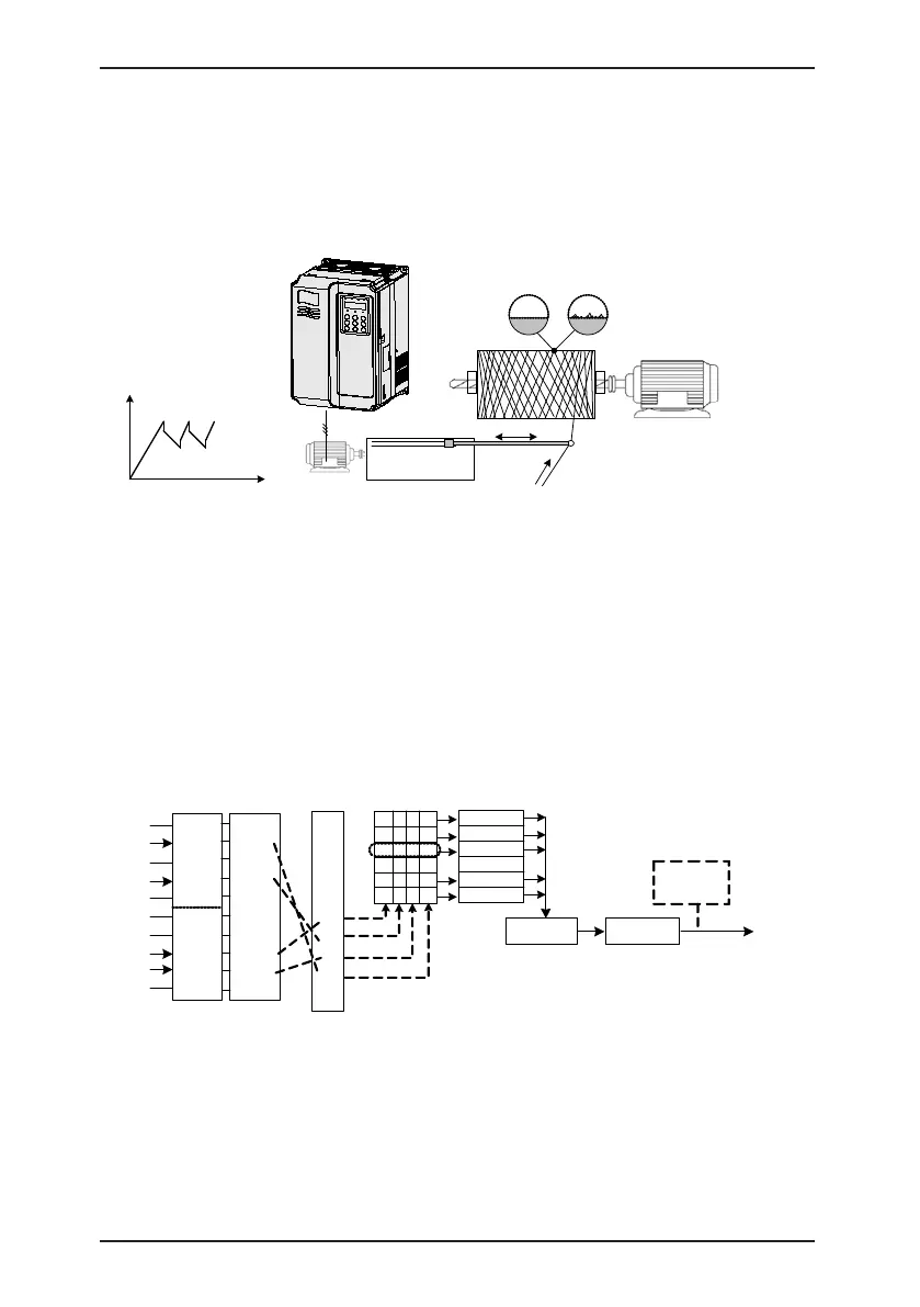
4.8.7 Swing Mode
For the textile and chemical ber processing equipment, the swing function improves the
uniform density of traversing and winding, as shown in Figure 4-24. The function is set in
FB-00 to FB-04. For details, see the description of these function codes.
Figure 4-24 Swing function
Winding motor rotates
at uniform linear speed
Reciprocating
mechanism
Swing frequency running
With swing
frequency
Without swing
frequency
Pendulum
motor
f
t
FB-01 > 0%
FB-02: Jump frequency
amplitude
FB-03: Swing frequency
cycle
FB-04: Triangular wave
rising time coefficient
4.8.8 Multi-Speed Mode
In scenarios where the running frequency of the AC drive need not be adjusted continuously
and only several frequencies are required, the multi-speed control can be used. The
MD380 supports a maximum of 16 running frequencies, which are implemented by state
combinations of four DI terminals. Set the function codes corresponding to DI terminals to a
value among 12 to 15, and then the DI terminals are specied as the multi-frequency input
terminals. The multiple frequencies are set based on the multi-frequency table in group
FC. In addition, you need to set F0-03 (Main frequency source X selection) to 6 (Multi-
reference). The following gure shows how to set the multi-speed function.
Figure 4-25 Setting the multi-speed function
F4-00
.
.
.
.
.
15
14
13
12
..
0 0 0 0
0 0 0 1
0 0 1 0
. .
1 1 1 0
1 1 1 1
FC-00
...
F0-03 = 6
Target
running
frequency
×
(F0-10)
0
1
Terminal
Function
code
Setting
value
State
combination
Multi-frequency
table
%
Maximum
frequency
Frequency
source selection
DI1
DI2
DI3
DI4
DI5
DI6
DI7
DI8
DI9
DI10
0
0
(Binary)
Select multi-reference as
the frequency source
F4-01
F4-02
F4-03
F4-04
F4-05
F4-06
F4-07
F4-08
F4-09
FC-01
FC-02
FC-14
FC-15
F0-07 = 0
F0-27 = 0
In the preceding figure, DI7, DI4, DI8, and DI2 are used as the multi-frequency input
terminals, each of which has a bit value. The state combinations of these terminals
correspond to multiple frequencies, When (DI7, DI4, DI8, DI2) = (0, 0, 1, 0), the state
combination value is 2, corresponding to the value set in FC-02. The target running
frequency is automatically calculated by FC-02 x F0-10.
The MD380 supports a maximum of four DI terminals to be used as the multi-frequency
input terminals. You can also use less than four DI terminals, and the empty bit is considered
to be 0.

 Loading...
