MD380 User Manual Function Code Table
- 85 -
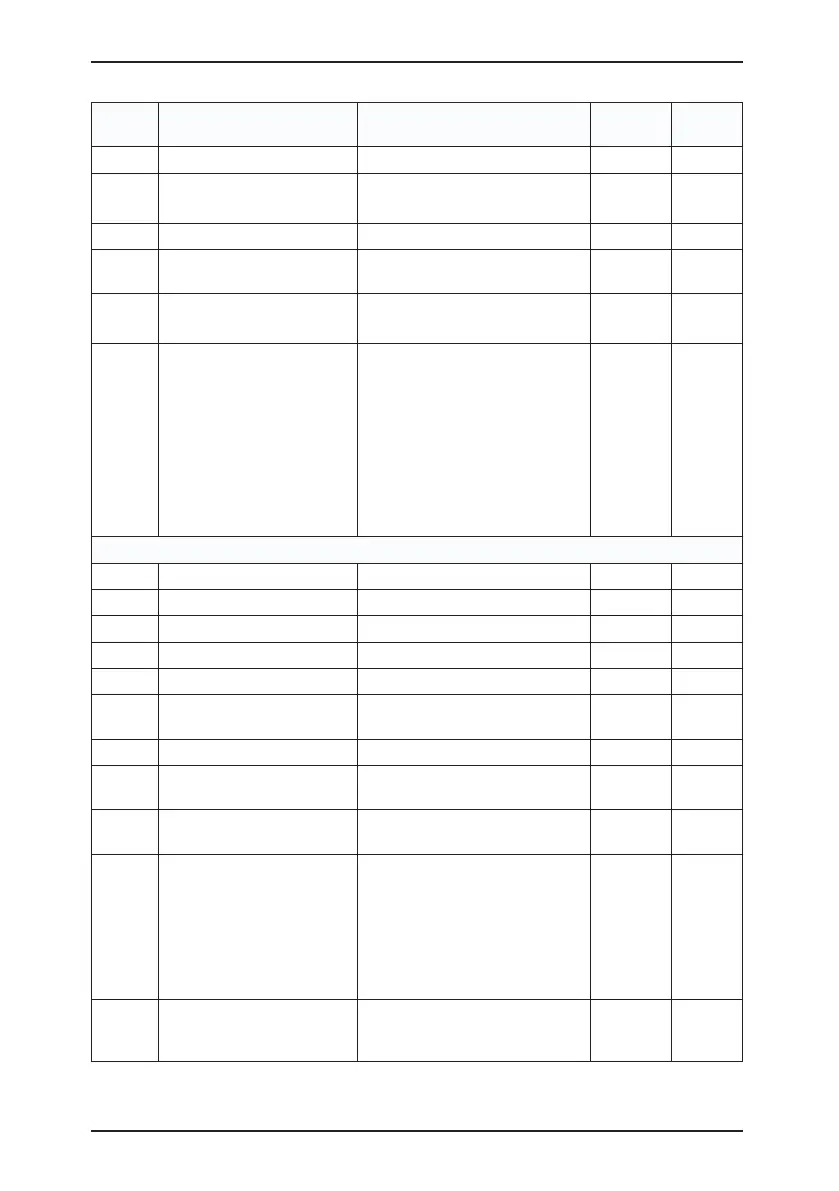
Function
Code
Parameter Name
Setting Range
Default Property
F1-31 Encoder installation angle
0.0°–359.9° 0.0°
★
F1-32
U, V, W phase sequence of
UVW encoder
0: Forward
1: Reverse
0 ★
F1-33 UVW encoder angle offset
0.0°–359.9° 0.0°
★
F1-34
Number of pole pairs of
resolver
1–65535
1 ★
F1-36
Encoder wire-break fault
detection time
0.0s: No action
0.1–10.0s
0.0s ★
F1-37 Auto-tuning selection
0: No auto-tuning
1: Asynchronous motor static
auto-tuning
2: Asynchronous motor complete
auto-tuning
11: Synchronous motor with-load
auto-tuning
12: Synchronous motor no-load
auto-tuning
0 ★
Group F2: Vector Control Parameters
F2-00
Speed loop proportional gain 1
0–100
30 ☆
F2-01
Speed loop integral time 1
0.01–10.00s
0.50s ☆
F2-02
Switchover frequency 1
0.00 to F2-05
5.00 Hz ☆
F2-03
Speed loop proportional gain 2
0–100
20 ☆
F2-04 Speed loop integral time 2
0.01–10.00s
1.00s ☆
F2-05 Switchover frequency 2
F2-02 to maximum output
frequency
10.00 Hz ☆
F2-06 Vector control slip gain
50%–200%
100% ☆
F2-07
Time constant of speed loop
lter
0.000–0.100s
0.000s ☆
F2-08
Vector control over-
excitation gain
0–200
64 ☆
F2-09
Torque upper limit source in
speed control mode
0: F2-10
1: AI1
2: AI2
3: AI3
4: Pulse setting (DI5)
5: Communication setting
0 ☆
F2-10
Digital setting of torque
upper limit in speed control
mode
0.0%–200.0%
150.0% ☆

 Loading...
