EasyManua.ls Logo

Inovance MD38CAN2 - User Manual

Inovance MD38CAN2
30 pages
Print Icon
To Next Page IconTo Next Page
Loading...
User Guide
MD38CAN2 (CANopen) Card
Optional Part for the MD Series Modular Vector AC Drive
MD38CAN2 (CANopen) Card User Guide
Copyright   Shenzhen Inovance Technology Co., Ltd.
Shenzhen Inovance Technology Co., Ltd.
Add.: Building E, Hongwei Industry Park, Liuxian Road, Baocheng No. 70 Zone, Baoan District, Shenzhen
Tel: +86-755-2979 9595
Fax: +86-755-2961 9897
Service Hotline: 400-777-1260
http: //www.inovance.com
Suzhou Inovance Technology Co., Ltd.
Add.: No. 16 Youxiang Road, Yuexi Town, Wuzhong District, Suzhou 215104, P.R. China
Tel: +86-512-6637 6666
Fax: +86-512-6285 6720
Service Hotline: 400-777-1260
http: //www.inovance.com
Min
A00
Data code 19010927
User Guide
Question and Answer IconNeed help?

Do you have a question about the Inovance MD38CAN2 and is the answer not in the manual?

Overview

The MD38CAN2 (CANopen) Card is a communication extension card designed for Inovance's MD series AC drives, serving as a field bus adapter. It enables the AC drive to connect to a high-speed CAN communication network and facilitates control via the field bus. CANopen is a universal field bus standard, allowing devices that support this protocol to access the CANopen network.

Function Description

The MD38CAN2 card integrates into the AC drive, providing CAN bus communication capabilities. It supports various communication objects and protocols essential for network management and data exchange.

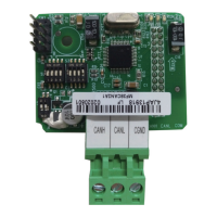
Hardware Layout and Interfaces: The card features a CN1 wiring terminal for CAN bus connection, comprising three interfaces: CANH (positive), CANL (negative), and CGND (shield). DIP switches S2 and S3 are used to configure the CAN communication baud rate and device address. DIP switch S1 is dedicated to setting the CAN bus termination resistor. Three LED indicators (PWR, ERR, RUN) provide visual feedback on the card's running state. SW1 is a factory test interface and should not be connected by users.

CAN Bus Connection: For CAN bus connection, shielded twisted pairs are recommended. The bus ends should be connected with two 120-Ω terminal matching resistors to prevent signal reflection. Single-point grounding is generally used for the shield. Inovance's PLCs and MDCAN2 devices are equipped with built-in resistors that can be enabled via DIP switches.

CAN Bus Transmission Distance: The maximum transmission distance of the CANopen bus is dependent on the baud rate and the communication cable used. For example, at 1 Mbps, the maximum bus length is 30m; at 500 Kbps, it's 80m; and at 250 Kbps or 125 Kbps, it's 150m.

DIP Switch Configuration:

  • Termination Resistor (S1): A 2-digit DIP switch sets the CAN bus termination resistor. Setting both switches to '1' connects the resistor, while setting both to '0' disconnects it. Termination resistors are recommended at both ends of the network topology.
  • Baud Rate (S2/S3 - Switches 1 & 2): These two switches determine the baud rate. Combinations of '00', '01', '10', and '11' correspond to 125 Kbps, 250 Kbps, 500 Kbps, and 1 Mbps, respectively.
  • CANopen Device Address (S2/S3 - Switches 3 to 8): Six switches (3 to 8) are used to set the CANopen device address, ranging from 1 to 63. Switch 3 is the highest bit, and switch 8 is the lowest. Address 0 is reserved and cannot be used.

State Indicators:

  • PWR (Red): ON indicates normal power-on; OFF indicates abnormal power-on (check installation).
  • ERR (Red): ON indicates internal AC drive communication timeout; Blinking quickly indicates incorrect CANopen address setting; Blinking twice indicates a CANopen emergency message (AC drive fault).
  • RUN (Green): ON indicates CANopen "Operational"; Blinking indicates CANopen "Pre-Operational"; OFF indicates CANopen "Stopped".

Software Features: The MD38CAN2 supports five main protocols:

  • NodeGuarding: Allows the master to query the device state.
  • Heartbeat: The slave periodically reports its current state to the master.
  • Service Data Object (SDO): Supports expedited transfer, transferring two bytes of a parameter at a time.
  • Process Data Objects (PDOs): Includes three transmit PDOs (TPDOs) and three receive PDOs (RPDOs) for real-time data exchange.
  • Emergency (EMCY) Objects: For reporting emergency messages.

COB-ID: The card uses pre-defined communication object identifiers (COB-IDs) which are fixed and cannot be changed. These include:

  • Network management (NMT) object: 0x000
  • Synchronization (SYNC) object: 0x080
  • SDO: Transmit (0x600+Node-Id), Receive (0x580+Node-Id)
  • PDO: RPDO1 (0x200+Node-Id), RPDO2 (0x300+Node-Id), RPDO3 (0x400+Node-Id), TPDO1 (0x180+Node-Id), TPDO2 (0x280+Node-Id), TPDO3 (0x380+Node-Id)
  • EMCY object: 0x80+Node-Id Node-Id is the device ID set by the DIP switch.

Parameter Operation of AC Drive: AC drive parameters are mapped to CANopen address indices. For example, F0-03 maps to object dictionary index 0x20F0 with subindex 0x04. Parameters are grouped (F0 to FF, A0 to AF, U0 to UF) with specific CANopen address ranges for read and write operations. The CANopen subindex is obtained by adding one to the parameter number. SDOs are used for read and write operations, with specific command codes and data formats for successful or failed operations.

PDO AC Drive Operation:

  • RPDO (Receive PDO): Three RPDOs (RPDO1, RPDO2, RPDO3) are supported for receiving control commands and set frequencies. For example, FE-00 for AC drive control command (Forward RUN, Reverse RUN, Jog, Coast to stop, Decelerate to stop, Fault reset) and FE-01 for AC drive set frequency.
  • TPDO (Transmit PDO): Three TPDOs (TPDO1, TPDO2, TPDO3) are supported for transmitting AC drive running state and frequency. For example, FE-20 for AC drive running state (fixed mapping) and FE-21 for AC drive running frequency. The running state includes bits for stop/run, forward/reverse, fault status, and set frequency reached.

Parameters Related to CANopen Communication:

  • CANopen Card Enabling: Parameter F0-28 (Communication extension card type) must be set to '1' to enable the CANopen card. F0-02 (Command source selection) should be set to '2' for communication control. F0-03 (Main frequency source X selection) should be set to '9' for communication setting.
  • Communication Control: Parameters like U3-16 (Frequency setting), U3-17 (Control command), U3-18 (DO control), U3-19 (AO1 control), U3-20 (AO2 control), U3-21 (FMP control), and U3-23 (Rotation speed control) are used for communication control.
  • Communication Monitoring: Parameters like U0-00 (Running frequency), U0-01 (Set frequency), U0-02 (Bus voltage), U0-03 (Output voltage), U0-04 (Output current), and many others provide monitoring data. U0-72 specifically tracks CAN bus disconnection times.

Emergency Message and AC Drive Fault Description: The card transmits 7-byte emergency messages. The emergency error code indicates communication errors or manufacturer-specified errors. The error register provides flags for error generation and communication errors. A manufacturer-specified error code corresponds to the AC drive fault code. A list of standard fault codes for the MD380 AC drive is provided, covering various operational issues.

Usage Features

Installation: The MD38CAN2 card is installed inside the Inovance AC drive. Before installation, power off the AC drive and wait approximately 10 minutes until the charging indicator turns OFF. Insert the card into the designated position and secure it with screws. It is crucial not to insert the card while the AC drive is powered on.

Parameter Operation: Users can perform SDO read-write operations to access and modify AC drive parameters. For repeated parameter rewriting, it is recommended to use the RAM mapping addresses to avoid damaging the EEPROM storage of the AC drive. Motor auto-tuning cannot be performed via communication parameter changes.

Network Management: The NMT master can send NMT Module ControlNMT messages to manage and monitor all nodes, including starting, stopping, resetting, and entering pre-operational states for remote nodes. NodeGuarding and Heartbeat messages are used for checking node states and ensuring data transmission availability.

Maintenance Features

Simple Diagnosis: The AC drive's parameter U0-72 provides a simple diagnostic tool by displaying the total number of CAN bus disconnections caused by strong interference since power-on.

Diagnosis and Troubleshooting:

  • If U0-72 shows a value greater than 0 but does not increase, strong interference occurred previously.
  • If U0-72 is greater than 0 and increases within 5 minutes, the network is experiencing strong interference or an incorrect configuration.
  • Troubleshooting Steps:
    • Verify that the baud rate and address configurations are consistent across all nodes, including the master controller, and that DIP switch settings are correct.
    • Check the termination resistors: ensure they are connected only at the two ends of the bus. Power off all devices and use a multimeter to measure the resistance between CANH and CANL; it should be between 50 and 60 Ω.
    • Confirm correct wiring: check that CANH and CANL are not reversely connected and that the bus terminal CGND is connected. Generally, only CGND of all devices needs to be connected, without grounding CGND itself.

Inovance MD38CAN2 Specifications

General IconGeneral
Product nameMD38CAN2
CategoryAdapter
ManufacturerInovance
Voltage24V DC
Protection LevelIP20
Communication protocolCAN
ProtocolCANopen
Humidity5% to 95% (non-condensing)