2 Installation and Setting
- 2 -
2 Installation and Setting
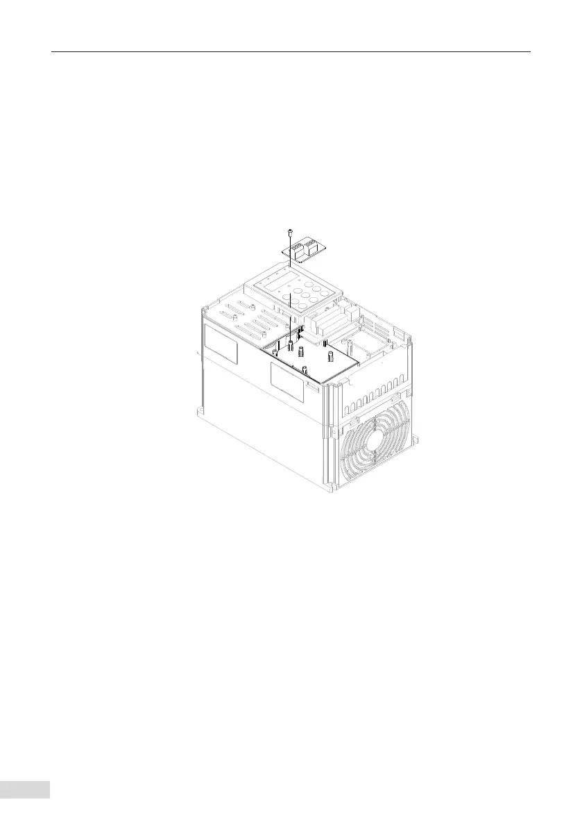
2.1 Installation of MD380CAN2
The MD38CAN2 card is installed inside Inovance's AC drive. Before the installation,
power o the AC drive, wait about 10 minutes until the charging indicator on the AC
drive becomes OFF, and insert the card in the position shown in the following gure.
Then, x the card with screws.
Note that the MD38CAN2 card cannot be inserted at power-on.
Figure 2-1 Installation of the MD38CAN2
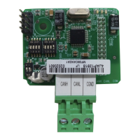
2.2 Hardware Layout
The following gure shows the hardware layout of the MD380CAN2. CN1 is the CAN bus
communication interface; DIP switch S1 is used to congure the CAN bus termination
resistor; DIP switches S2 and S3 are used to set the baud rate and address for CAN
communication; the three LED indicators indicate the running state; SW1 is the factory
test interface, and do not connect it.
 Loading...