2 Installation and Setting
- 3 -
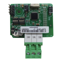
Figure 2-2 Hardware layout of the MD38CAN2
Mark Hardware Name Function Description
SW1 SW1 pin header It is used for the factory test. Do not connect it.
S2/S3 DIP switch
It is used to set the baud rate and address for CAN
communication.
S1 Termination resistor setting It is used to set the termination resistor.
J1
Interface for connecting AC
drive
It is used to connect the card to the AC drive.
H Screw xing hole
It is used to x the card with the M3*8 self-taping
screw.
CN1 Wiring terminal It is the CANopen bus wiring terminal.
LED State indicator
The three indicators are used to indicate the
running state.
2.3 Interface Description
1) Communication interface
Terminal CN1 is used to connect the CAN bus. It includes three interfaces, as described
in Table 2.1.
Table 2-1 Interface description of CN1
No. Mark Description
1 CANH Connect positive of the CAN bus.
2 CANL Connect negative of the CAN bus.
3 CGND Connect the shield of the CAN bus.
 Loading...