LCR-800 Series User Manual
28
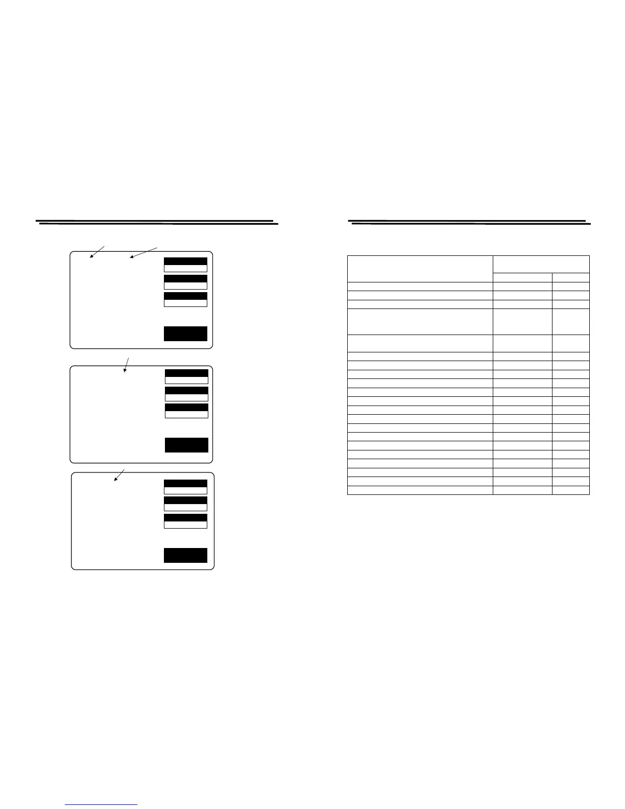
MOMORY
1
VOLT
1.000
AVGE
1
EXIT
STORE NO:
VOLTAGE = 1.000 V
AVERAGE = 1
MOMORY
1
VOLT
1.000
AVGE
1
EXIT
(1)RECALL:(2)STORE
VOLTAGE = 1.000 V
AVERAGE = 1
Press compound key 1 to
select the memory recall
function
MOMORY
1
VOLT
1.000
AVGE
1
EXIT
RECALL NO:
VOLTAGE = 1.000 V
AVERAGE = 1
Input number of desired memory block for memory recall function
Press compound key 2 to
select the memory store
function
Input number of desired memory block for memory store function
Figure 4-12. Programming of memory store/recall. (Cont.)
LCR-800 Series User Manual
29
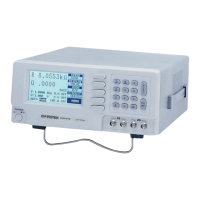
4-5-9. Handler Interface(Only for LCR-826/827/829)
HANDLER
INTERFACEFUNCTION
Signal Name Pin NO.
Start Measurement(I) /I_E_TRIG 24
End of test(O) /O_EOM 23
Data acquisition over , DUT removal OK.(O) /O_INDEX 22
RLC FAIL(O) /O_P_HI
/O_P_LO
/O_P_OVER
19
20
15
No-Go , D or Q Fail /O_S_REJ
/O_S_OVER
21
14
Go , BIN 1 Judgement /O_BIN_ 1 1
Go , BIN 2 Judgement /O_BIN _2 2
Go , BIN 3 Judgement /O_BIN_ 3 3
Go , BIN 4 Judgement /O_BIN_ 4 4
Go , BIN 5 Judgement /O_BIN_ 5 5
Go , BIN 6 Judgement /O_BIN_ 6 6
Go , BIN 7 Judgement /O_BIN_ 7 7
Go , BIN 8 Judgement /O_BIN_ 8 8
Go , BIN 9 Judgement /O_BIN_ 9 9
Go , BIN 10 Judgement /O_BIN_ 10 10
Go , BIN 11 Judgement /O_BIN_ 11 11
Go , BIN 12 Judgement /O_BIN_ 12 12
Go , BIN 13 Judgement /O_BIN_ 13 13
Panel Lock /I_K_LOCK 25
GND GND 16,18
VCC VCC 17