25
Product Support: www.instron.com
Chapter 3
Installation
This chapter describes electromechanical and servohydraulic load string attachment
methods and grip installation procedures. Each procedure contains an equipment list, a
checklist and a set of instructions.
• General. . . . . . . . . . . . . . . . . . . . . . . . . . . . . . . . . . . . . . . . . . . . . . . . . . . . . . . . . . . 25
• Installing the Jaw Faces . . . . . . . . . . . . . . . . . . . . . . . . . . . . . . . . . . . . . . . . . . . . . 27
• Installing the Spacers and Side Plates . . . . . . . . . . . . . . . . . . . . . . . . . . . . . . . . . 29
• Preloading the Load String . . . . . . . . . . . . . . . . . . . . . . . . . . . . . . . . . . . . . . . . . . . 32
• Removing Preload . . . . . . . . . . . . . . . . . . . . . . . . . . . . . . . . . . . . . . . . . . . . . . . . . . 33
General
Load String
The load string is all of the components you install between a force producing load
frame component (actuator or moving crosshead) and a stationary rigid member
(baseplate or fixed crosshead). This includes the grips, attachment kits and the
specimen. A tight connection between each component is essential for accurate test
data. Any backlash in the load string components will degrade the integrity of the test
results.
Each grip requires an attachment kit to connect the grip to either the load cell, actuator
or crosshead. The type of attachment kit will depend on the type of test system, either
servohydraulic or electromechanical, and the size of the load cell, actuator or
crosshead. In either case, you must preload the load string with a tensile force 10 to
15% greater than the highest load your test will reach.
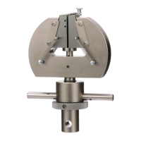
Clevis Pin Couplings
A clevis pin coupling is typically used for attaching the grips to an electromechanical test
system. Figure 5 on page 26 illustrates the clevis pin coupling. A male shank connects
to a female clevis socket, which connects to either the load cell or to the baseplate. A