Do you have a question about the Integra RDC-7 and is the answer not in the manual?
Critical components for fire/shock risk. Replace with Onkyo parts.
Ensure exposed parts are insulated before returning to customer.
Covers tuning range, sensitivity, selectivity, and distortion.
Procedure for replacing internal fuses, including part numbers and voltage models.
Steps to reset the microprocessor and return to factory settings.
Procedure for safety checks, specifically for USA models, using an insulation tester.
Details connecting a computer via RS232C for control or programming.
Explanation of the remote control buttons and their functions.
Guide to rear panel terminals and their usage.
Examples for connecting turntables, CD players, and tape decks.
Examples for connecting DVD players, LD players, VCRs, and tuners.
Steps to remove the front panel assembly.
Steps to remove the rear panel and lists associated screws/PC boards.
Procedure for attaching door base, cushions, and stays.
Pins with special functions during configuration or operation.
Table detailing flash memory pins and their functions.
Overview of internal PC board connections.
Diagram showing assembly breakdown of the chassis.
Detailed list of chassis parts by reference number.
Diagram showing connections to the sub microprocessor.
Detailed list of sub microprocessor terminals and functions.
Continued list of sub microprocessor terminals and functions.
Diagrams showing connections between various PC boards.
Overall system block diagram of the RDC-7.
Circuit diagram for the U1 board.
Circuit diagram for the U1 board (part 2).
Detailed list of chassis parts related to the exploded view.
Component layout for U10 main microprocessor board.
Procedure for entering and operating the test mode.
Procedure to confirm flash memory read/write operation.
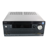
| Brand | Integra |
|---|---|
| Model | RDC-7 |
| Category | Controller |
| Language | English |