39
1
2
3
4
5
6
7
8
9
10
11
12
13
14
15
16
18
19
20
21
22
23
24
25
26
27
28
29
30
31
32
33
34
35
36
37
38
39
40
41
42
43
44
45
46
47
48
49
50
FDATA
FCLK
CFSTB
TDATA
TCLK
~TCS1
~TCS2
VSS
VSS
VPDATA
VPCLK
~RESET
XOUT
VSS
XIN
VCC
VSTB
~RDSSCK
~POFF
PLLCE
RDSDATA
RDSSIG
~STEREO
~SD
DIGSO
DIGSI
DIGSCK
~INTRQ1
~INTRQ2
2NDPLLCS
2NDPLLLOCK
~AD/DIR
~SUBREQ
MAINSO
MAINSI
MAINSCK
~MAINREQ
XSTATE
ERROR
CSFLAG
~RFDIRRST
RFSYNC
~DARST
~ADRST
DFS
APGLOCK
F0
O
O
O
O
O
O
O
I
I
O
O
I
O
I
I
I
O
I
I
O
I
I
I
I
O
I
O
I
I
O
I
O
I
O
I
O
O
I
I
I
O
I
O
O
O
I
O
H
CLK
H
H
CLK
L
L
H
CLK
H
CLK
L
H
H
H
L
L
H
H
CLK
L
L
H
H
H
L
H
H
CLK
L
H
H
H
L
H
L
L
H
H
H
Serial data output terminal of function switch for input and configuration.
Serial clock output terminal of function switch for input and configuration.
Serial clock output terminal of function switch for configuration.
Serial data output terminal of tone control IC.
Serial clock output terminal of tone control IC.
Chip select output terminal of tone control IC for front channel.
Serial data output terminal of tone control IC for center and sub woofer.
Input terminal to switch the bus width of external data. Connect to the ground.
Input terminal to switch processor mode. Connect to the ground.
Serial data output terminal of electrical volume and PLL ICs.
Serial clock output terminal of electrical volume and PLL ICs.
System reset input terminal.
Oscillator circuit output terminal of main clock.
Power supply terminal. Connect to the ground.
Oscillator circuit input terminal of main clock.
Power supply terminal. Connect to +5V.
Strobe output terminal of electrical volume.
Clock input terminal from RDS modulator IC.
Input terminal for power failure detection.
Strobe output terminal of PLL IC.
DATA input terminal from RDS modulator IC.
Signal strength detection terminal of tuner.
FM stereo broadcast detection terminal.
Signal strength detection terminal of tuner.
Serial data output terminal to DSP ICs.
Serial data input terminal from DSP and DIR ICs.
Serial clock output terminal to DSP ICs.
INTRQ input terminal from DSP2.
INTRQ input terminal from DSP1.
Serial chip select output terminal of second PLL IC.
Lock detection input terminal from second PLL IC
ADC/DIR select output terminal
Request input terminal from sub microprocessor
Serial data output terminal of sub microprocessor
Serial data input terminal from sub microprocessor
Serial clock output terminal of sub microprocessor
Request output terminal from sub microprocessor
Source clock change monitor input terminal (DIR)
Flag input terminal for PLL lock error or data error.
Port of flash memory rewriting (DIR)
Update flag input terminal of head 40 bits of channel status
DIR/AC-3 RF RESET output terminal (common)
Synchronizing input terminal for AC-3 RF
Reset signal output terminal for DAC
Port of flash memory rewriting (DIR)
Reset signal output terminal for ADC
Sampling frequency control output terminal for ADC/DAC
Lock ok signal detection terminal of apgee master clock unit.
Sampling frequency control output terminal for Gate array (Q8704)
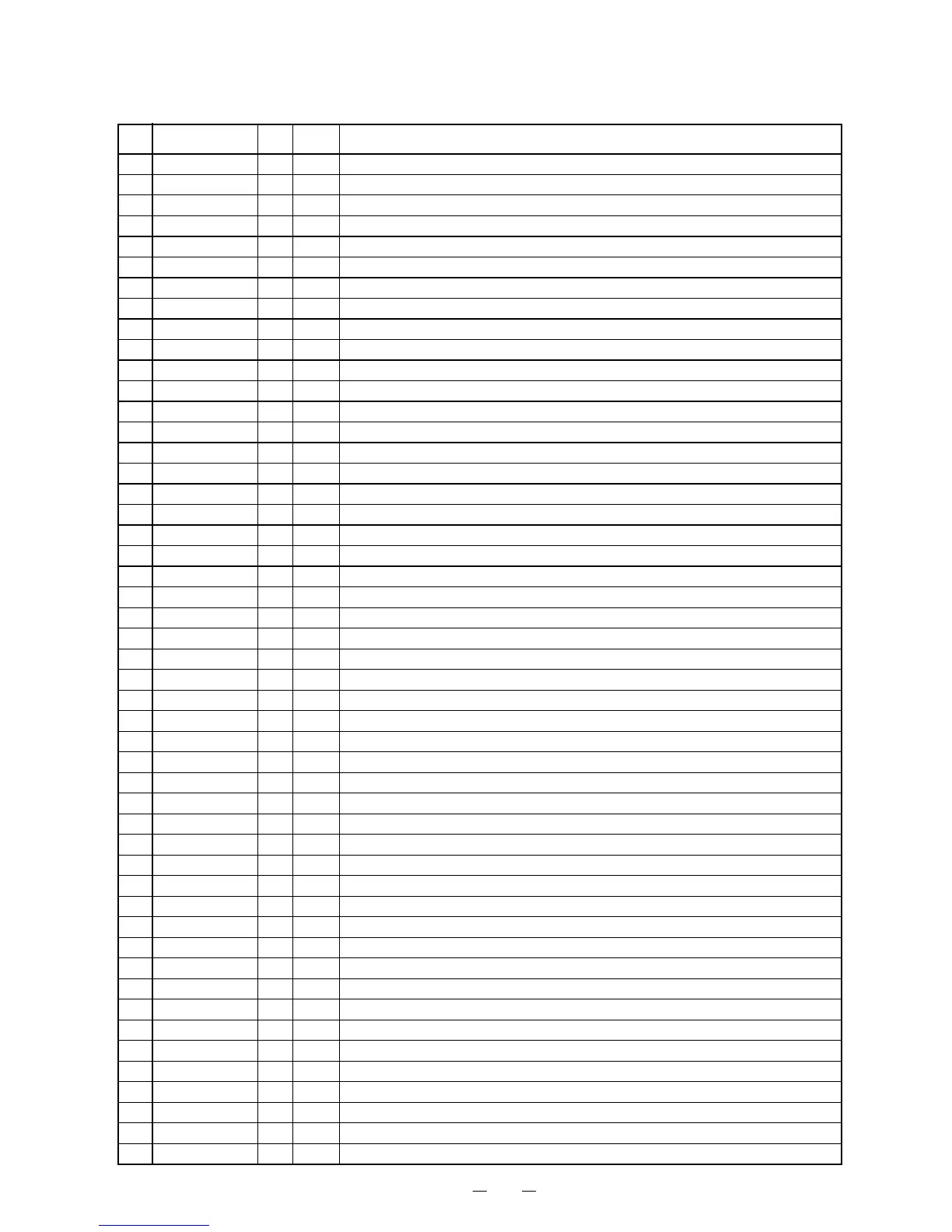
No. Function I/O Act. Description
MAIN MICROPROCESSOR TERMINAL DESCRIPTION
Q7001 : M30624FGFP