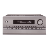
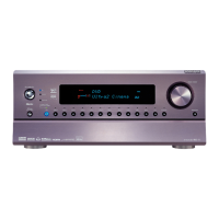
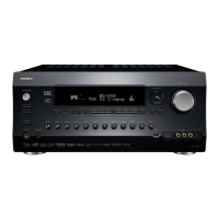
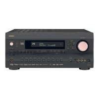
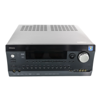
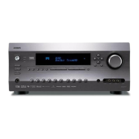
RDC-7
6
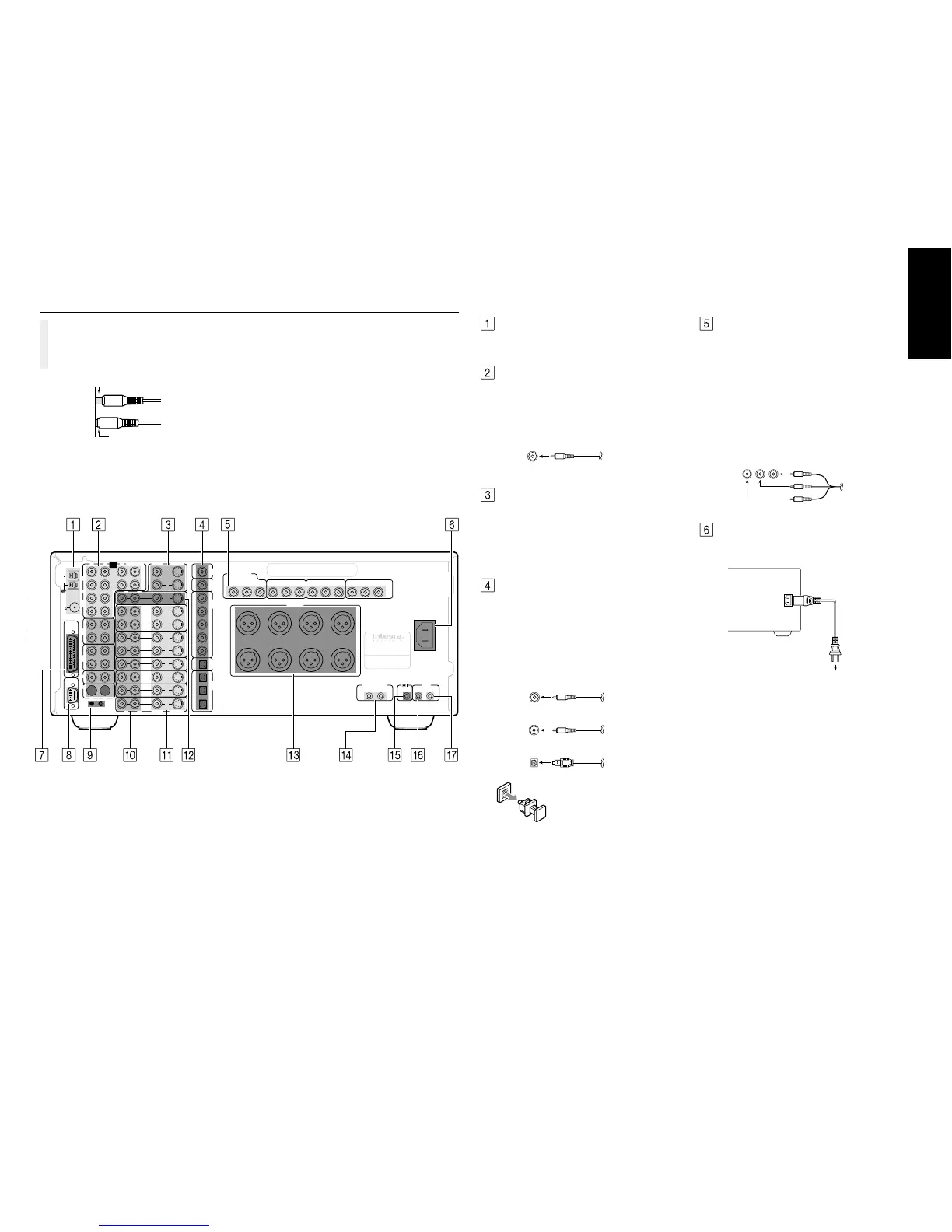
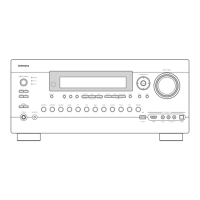
Rear panel facilities
Improper connection
Inserted completely
Here is an explanation of the terminals found on the
rear of the RDC-7 and how they are used. Before
connecting your audio and video components, be
sure to read this section carefully and then proceed
to the explanations on how to connect each indi-
vidual component.
¥ Be sure to always refer to the instructions that came
with the component that you are connecting.
¥ Do not plug in the power cord until all connections
have been made.
¥ For input jacks, red connectors (marked R) are used
for the right channel, white connectors (marked L)
are used for the left channel, and yellow connectors
(marked V) are used for video connection.
¥ Insert all plugs and connectors securely. Improper
connections can result in noise, poor performance,
or damage to the equipment.
¥ Do not bind audio/video connection cables with
power cords and speaker cables. Doing so may
adversely affect the picture and sound quality.
DVD
VIDEO
5
VIDEO
4
VIDEO
3
ZONE 2
MONITOR
OUT
VIDEO
1
VIDEO
2
R
L
R
L
C
SUBWOOFER
IR IN
MAIN ZONE 2
VIDEO
S VIDEO
VIDEO
S VIDEO
INPUT 2
P
B
P
R
Y
INPUT 3
P
B
P
R
Y
OUTPUT
P
B
P
R
Y
OUT
OUT
IN
IN
IN
IN
IN
IN
AC
INLET
OUT
1
2
FM
ANT.
75
AM
ANT.
C
D
GND
MULTI
CHANNEL
INPUT
RS 232
TAPE
2
TAPE
1
FRONT
3
2
1
3
2
5
4
1
I
N
I
N
I
N
I
N
OUT
OUT
L
R
L
1
2
1
2
1
2
1
2
R
COMPONENT
VIDEO
INPUT 1
P
B
P
R
Y
DIGITAL
OUTPUT
(
COAXIAL
)
AC-3
RF
DIGITAL
INPUT
(
COAXIAL
)
DIGITAL
OUTPUT
(
OPTICAL
)
DIGITAL
INPUT
(
OPTICAL
)
PHONO
SURR
BACK
SURR
PRE
OUT
RIGHT CENTER SUBWOOFER
SURROUND
RIGHT
SURROUND
LEFT
SURROUND BACK
RIGHT
SURROUND BACK
LEFT
LEFT
PRE OUT
AV CONTROLLER
MODEL NO.
RDC-7
12V TRIGGER
AB
COMPONENT VIDEO INPUT/OUTPUT
If your DVD player or other device has component
video connectors, be sure to connect them to these
component video connectors on the RDC-7. The RDC-
7 has three component video input connectors to ob-
tain the color information (Y, P
B, PR) directly from the
recorded DVD signal or other video component and
one component video output connector to output it
directly into the matrix decoder of the display device.
By sending the pure DVD component video signal di-
rectly, the DVD signal forgoes the extra processing that
normally would degrade the image. The result is vastly
increased image quality, with incredibly lifelike colors
and crisp detail.
YPB PR RCA type
¥ When using the digital inputs and outputs, make
sure to also connect the analog connections when-
ever possible.
¥ When using one of the optical input or output jacks,
remove the protective cap and keep it safely.
When the jack is not used, replace the protective
cap.
¥ When using an optical input or output jack, always
use an optical fiber cable.
RCA type
COAXIAL Coaxial cable
AC-3RF Coaxial cable
OPTICAL Optical fiber cable
Optical digital input terminal
An optical digital input terminal is
equipped with a protection cap.
When connecting, remove this cap.
When not using, put the cap back
on the terminal.
Power cord
(supplied)
To an AC
wall outlet
AC INLET
Plug the supplied power cord into this AC INLET and
then into the power outlet on the wall.
¥ Do not use a power cord other than the one sup-
plied with the RDC-7. The power cord supplied is
designed for use with the RDC-7 and should not be
used with any other device.
¥ Never have the power cord disconnected from the
RDC-7 while the other end is plugged into the wall
outlet. Doing so may cause an electric shock. Al-
ways connect by plugging into the wall outlet last
and disconnect by unplugging from the wall outlet
first.
ANTENNA
These jacks are for connecting the FM indoor antenna
and AM loop antenna that are supplied with the RDC-
7.
PRE OUT (RCA type)
These jacks are for connecting power amplifiers. If the
jacks on your power amplifier are RCA type jacks, con-
nect them here. Two terminals are provided for each of
the front left, center, and right channels. The same sig-
nal is output from both terminals 1 and 2.
DIGITAL INPUT/OUTPUT
(coaxial, optical, and input-only AC-3RF)
These are the digital audio inputs and outputs. There
are 5 digital inputs with coaxial jacks, 3 with optical
jacks, and 1 AC-3RF input. The inputs accept digital
audio signals from a compact disc, LD, DVD, or other
digital source component. For digital output, there is 1
coaxial output and 1 optical output. The digital outputs
can be connected to MD recorders, CD recorders, DAT
decks, or other similar components.
MONITOR OUT
There are 2 monitor outputs and each one includes
both composite video and S-video configurations.
When connecting two video monitors or televisions, be
aware that the OSD interface can only be used with
MONITOR OUT 1 (OSD will not be displayed on the
video monitor connected to MONITOR OUT 2).