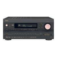
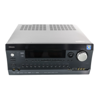
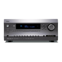
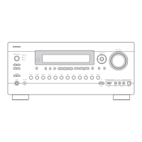
RDC-7
3
SERVICE PROCEDURE
1. Replacing the fuses
3. Safety-check out
(Only U.S.A. model)
After correcting the original service problem perform the
follwing safety check before releasing the set to the customer
Connect the insulating-resistance tester between the plug of
power supply cord and terminal GND on the back panel.
Specifications: More than 10Mohm at 500V
REF.NO.
PART NO.
DESCRIPTION
NOTE :
<UDD> : 120 V model only
<UDT> : Asian model only for 120V
<UPP> : European model only
<UPT> : Asian model only for 230V
<UGT> : 220V model only
This symbol located near the fuse indicates that the
fuse used is show operating type, For continued protection against
fire hazard, replace with same type fuse , For fuse rating, refer to
the marking adjest to the symbol.
Ce symbole indique que le fusible utilise est e lent.
Pour une protection permanente, n'utiliser que des fusibles de meme
type. Ce demier est indique la qu le present symbol est apposre.
This device employs a microprocessor to perform various
functions and operations. If interference generated by an external
power supply, radio wave, or other electrical souce results in accident
which causes the specified operations and functions to pperate
abnormally.
To perform a result, please follow the procesure below.
1. Turn teh Power switch to on.
2. Press and the hold down the VIDEO-1 button, then press the
STANDBY/ON button.
2. After " clear " is displayed, the preset memory and each
mode stored in the memory, such as surround, are initialized and
will return to the factory setting
3. Press the STANDBY/ON button.
4. Disconnect the power supply cord.
2.
To initialize the unit
4. Memory Preservation
This unit does not require memory preservation batteries. A built-in
memory power back-up system preserves the contents of the
memory during power failures and even when the unit is un-plugged.
The unit must be plugged in order to charge the back-up
system.
The memory preservation period after the unit has been unplugged
varies depending on climate and placement of the unit. On the
average, memory contents are protected over a period of a few
weeks after the last time the unit has been unplugged. This period
is shorter when the unit is exposed to a highly humid climate.
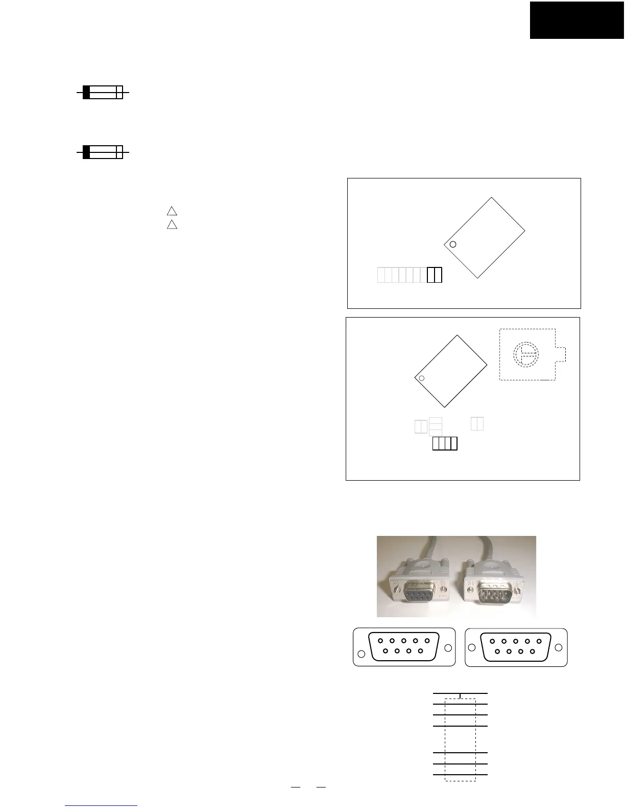
5. Changing the AM band step
When you change the band step, change the parts as shown below.
To 10kHz To 9kHz
R7091 Short Open
R7191 Open 10 kohms
R7276 Short Open
R7277 Short Open
R7376 Open 10kohms
R7377 Open 10 kohms
R7091
R7191
100
Q7001
MAIN MICROPROCESSOR
MAIN MICROPROCESSOR PC BOARD
NAAR-6837
From soldering side
SUB MICROPROCESSOR PC BOARD
NADIS-6832
From soldering side
Q7201
SUB MICROPROCESSOR
S7641
R7277
R7376
R7276
R7377
F9001 252163 ! 4A-UL/T-237, Fuse <UDD, UDT>
F9002 252074 ! 2A-SE-EAK, Fuse <UPP,UPT, UGT>
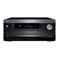
6. Connection of computer
When you change the program of microprocessor or control the unit
by the computer, connect the cable RS232C of straight type between
a computer and terminal RS232C on the rear panel.
12345
6789
54321
9876
To the unitTo PC
GND
GND
1
2
3
7
8
9
1
2
3
7
8
9