29
80960KB
3.3 Package Thermal Specification
The 80960KB is specified for operation when case
temperature is within the range 0°C to 85°C (PGA)
or 0°C to 100°C (PQFP). Measure case temperature
at the top center of the package. Ambient temper-
ature can be calculated from:
• T
J
= T
C
+ P*θ
jc
• T
A
= T
J
+ P*θ
ja
• T
C
= T
A
+ P*[θ
ja
−θ
jc
]
Values for θ
ja
and θ
jc
for various airflows are given in
Table 12 for the PGA package and in Table 12 for
the PQFP package. The PGA’s θ
ja
can be reduced
by adding a heatsink. For the PQFP, however, a
heatsink is not generally used since the device is
intended to be surface mounted.
Maximum allowable ambient temperature (T
A
)
permitted without exceeding T
C
is shown by the
graphs in Figures 23, 24, 25 and 26. The curves
assume the maximum permitted supply current (I
CC
)
at each speed, V
CC
of +5.0 V and a T
CASE
of +85°C
(P
GA) or +100°C (PQFP).
If the 80960KB is to be used in a harsh environment
where the ambient temperature may exceed the
limits for the normal commercial part, consider using
an extended temperature device. These
components
are available at 16, 20 and 25 MHz in
the ceramic PGA package. Extended operating
temperature
range is –40° C to +125°C (case).
Figure 26 shows the maximum allowable ambient
temperature for the 20 MHz extended temperature
TA80960KB at various airflows. The curve assumes
an I
CC
of 420 mA, V
CC
of 5.0 V and a T
CASE
of
+125°C.
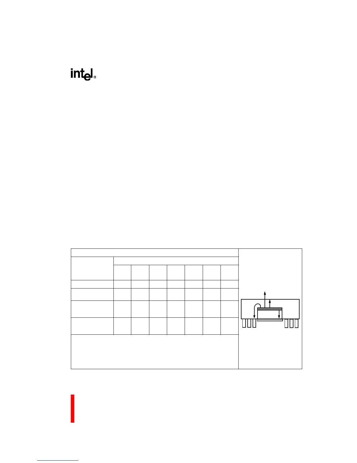
Table 14. 80960KB PGA Package Thermal Characteristics
Th
ermal Resistance — °C/Watt
Parameter
Airflow — ft./min (m/sec)
0
(0)
50
(0.25)
100
(0.50)
200
(1.01)
400
(2.03)
600
(3.04)
800
(4.06)
θ Junction-to-Case
2 2 2 2 2 2 2
θ Case-to-Ambient
(No Heatsink)
19 18 17 15 12 10 9
θ Case-to-Ambient
(Omnidirectional
Heatsink)
16 15 14 12 9 7 6
θ Case-to-Ambient
(Unidirectional Heat-
sink)
15 14 13 11 8 6 5
NOTES:
1. This table applies to 80960KB PGA plugged into socket or soldered directly to board.
2. θ
JA
= θ
JC
+ θ
CA
3. θ
J-CAP
= 4°C/W (approx.)
θ
J-PIN
= 4°C/W (inner pins) (approx.)
θ
J-PIN
= 8°C/W (outer pins) (approx.)
θ
JC
θ
JA
θ
J-PIN
θ
J-CAP