80960KB
10
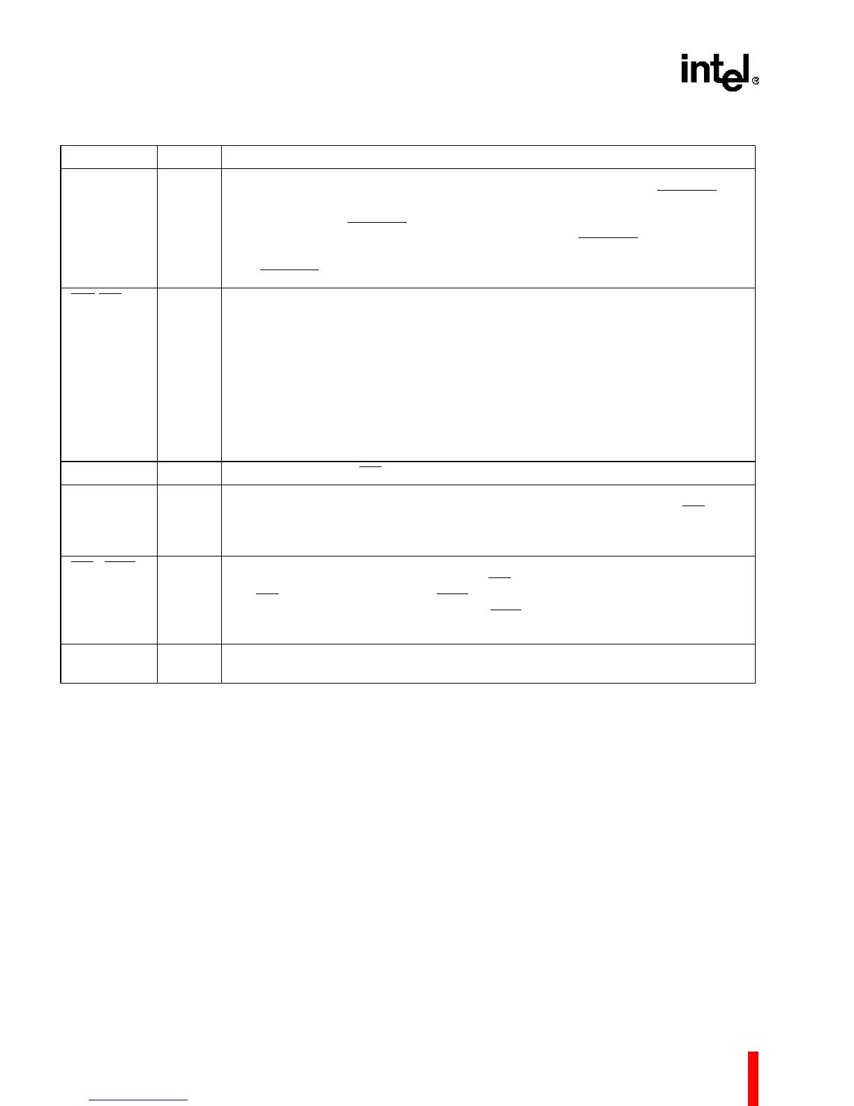
FAILURE O
O.D.
INITIALIZATION FAILURE indicates that the processor did not initialize correctly.
After RESET deasserts and before the first bus transaction begins, FAILURE
asserts while the processor performs a self-test. If the self-test completes
successfully, then FAILURE
deasserts. The processor then performs a zero
checksum on the first eight words of memory. If it fails, FAILURE
asserts for a
second time and remains asserted. If it passes, system initialization continues
and FAILURE
remains deasserted.
IAC
/INT
0
I INTERAGENT COMMUNICATION REQUEST/INTERRUPT 0 indicates an IAC
message or an interrupt is pending. The bus interrupt control register determines
how the signal is interpreted. To signal an interrupt or IAC request in a
synchronous system, this pin — as well as the other interrupt pins — must be
enabled by being deasserted for at least one bus cycle and then asserted for at
least one additional bus cycle. In an asynchronous system the pin must remain
deasserted for at least two bus cycles and then asserted for at least two more bus
cycles.
During system reset, this signal must be in the logic high condition to enable
normal processor operation. The logic low condition is reserved.
INT
1
I INTERRUPT 1, like INT
0
, provides direct interrupt signaling.
INT
2
/INTR I INTERRUPT2/INTERRUPT REQUEST: The interrupt control register determines
how this pin is interpreted. If INT
2
, it has the same interpretation as the INT
0
and
INT
1
pins. If INTR, it is used to receive an interrupt request from an external
interrupt controller.
INT
3
/INTA I/O
O.D.
INTERRUPT3/INTERRUPT ACKNOWLEDGE: The bus interrupt control register
determines how this pin is interpreted. If INT
3
, it has the same interpretation as
the INT
0
, INT1 and INT2 pins. If INTA, it is used as an output to control
interrupt-acknowledge transactions. The INTA
output is latched on-chip and
remains valid during T
d
cycles; as an output, it is open-drain.
N.C. N/A NOT CONNECTED indicates pins should not be connected. Never connect any
pin marked N.C. as these pins may be reserved for factory use.
Table 5. 80960KB Pin Description: Support Signals (Sheet 2 of 2)
NAME TYPE DESCRIPTION
I/O = Input/Output, O = Output, I = Input, O.D. = Open Drain, T.S. = Three-state
2.0 ELECTRICAL SPECIFICATIONS
2.1 Power and Grounding
The 80960KB is implemented in CHMOS IV
technology and therefore has modest power require-
ments. Its high clock frequency and numerous
output buffers (address/data, control, error and
arbitration signals) can cause power surges as
multiple output buffers simultaneously drive new
signal levels. For clean on-chip power distribution,
V
CC
and V
SS
pins separately feed the device’s
functional units. Power and ground connections
must be made to all 80960KB power and ground
pins. On the circuit board, all V
cc
pins must be
strapped closely together, preferably on a power
plane; all V
ss
pins should be strapped together,
preferably on a ground plane.
2.2 Power Decoupling
Recommendations
Place a liberal amount of decoupling capacitance
near the 80960KB. When driving the L-bus the
processor can cause transient power surges, partic-
ularly when connected to a large capacitive load.