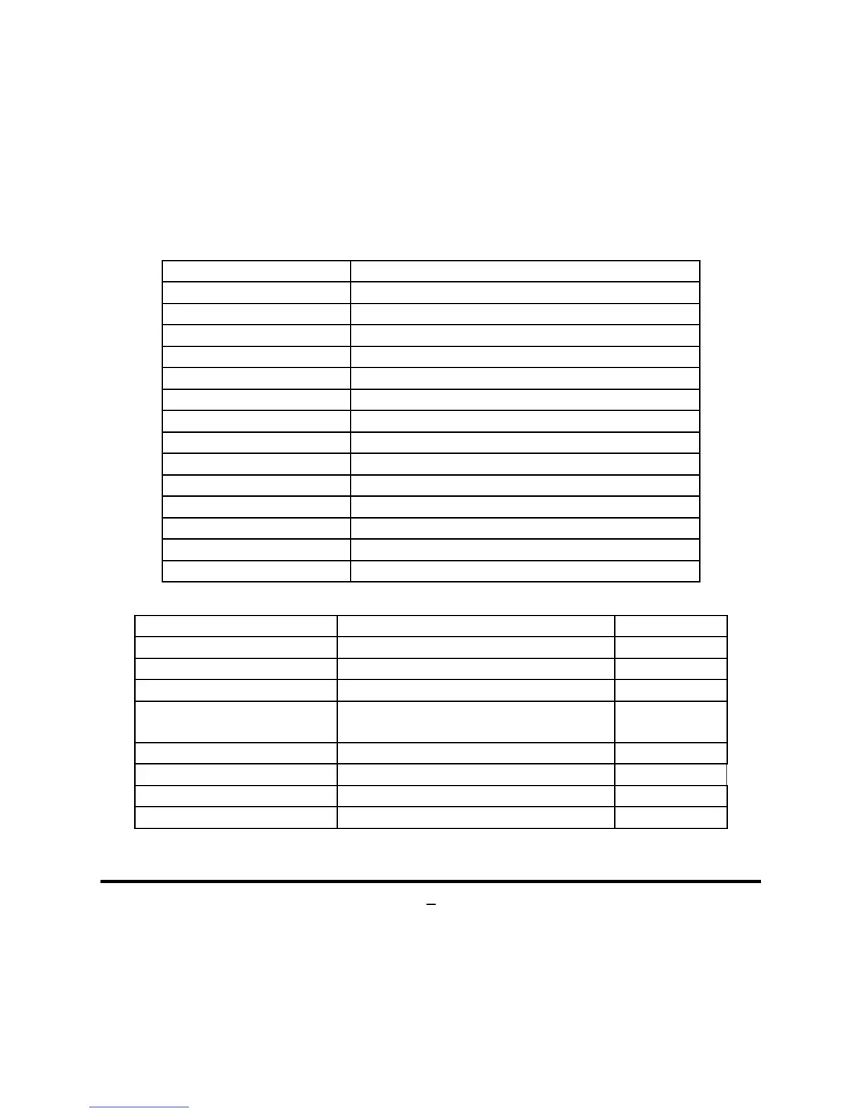
Connectors
Connector Name
ATXPWR 24-pin Main Power Connector
KB/MS(Top) PS/2 Mouse Connector
KB/MS(Bottom) PS/2 Keyboard Connector
VGA Video Graphic Attach Connector
DVI DVI-D Connector
USB3_0 USB 3.0 Port Connector
UL1(Middle & Bottom)
USB 2.0 Port Connector x2
UL1(Top) RJ-45 LAN Connector
AUDIO (Top) Audio Line In Connector
AUDIO (Middle) Audio Line Out Connector
AUDIO (Bottom) Audio MIC Connector
SATA2 SATAII Connector
MINIPE Full-size Mini-PCIE Connector
MSATA Full-size Mini-SATA Connector
Headers
Header Name Description
FP_AUDIO Front Panel Audio Header 9-pin Block
HDMI_SPDIF HDMI_SPDIF Out Header 2-pin Block
COM Serial Port Header 9-pin Block
JW_FP
Front Panel Header(PWR LED/ HD
LED/Power Button /Reset)
9-pin Block
LVDS LVDS Header 30-pin Block
INVERTER LVDS Inverter 6-pin Block
CPUFAN CPUFAN Header 4-pin Block
SYSFAN SYSFAN Header 3-pin Block
 Loading...