Intel Desktop Board DP55WG Product Guide
56
1. Observe the precautions in "Before You Begin" on page 29.
2. Connect the 12 V processor core voltage power supply cable to the 2 x 4 pin
connector (Figure 30, A) .
3. Con
nect the main power supply cable to the 2 x 12 pin connector (Figure 30, C).
4. If additional power is required for g
raphics cards, connect the appropriate power
supply cable to the SATA-style PCI Express graphics auxiliary power connector.
Setting the BIOS Configuration Jumper
NOTE
Always turn off the power and unplug the power cord from the computer before
moving the jumper. Moving the jumper with the power on may result in unreliable
computer operation.
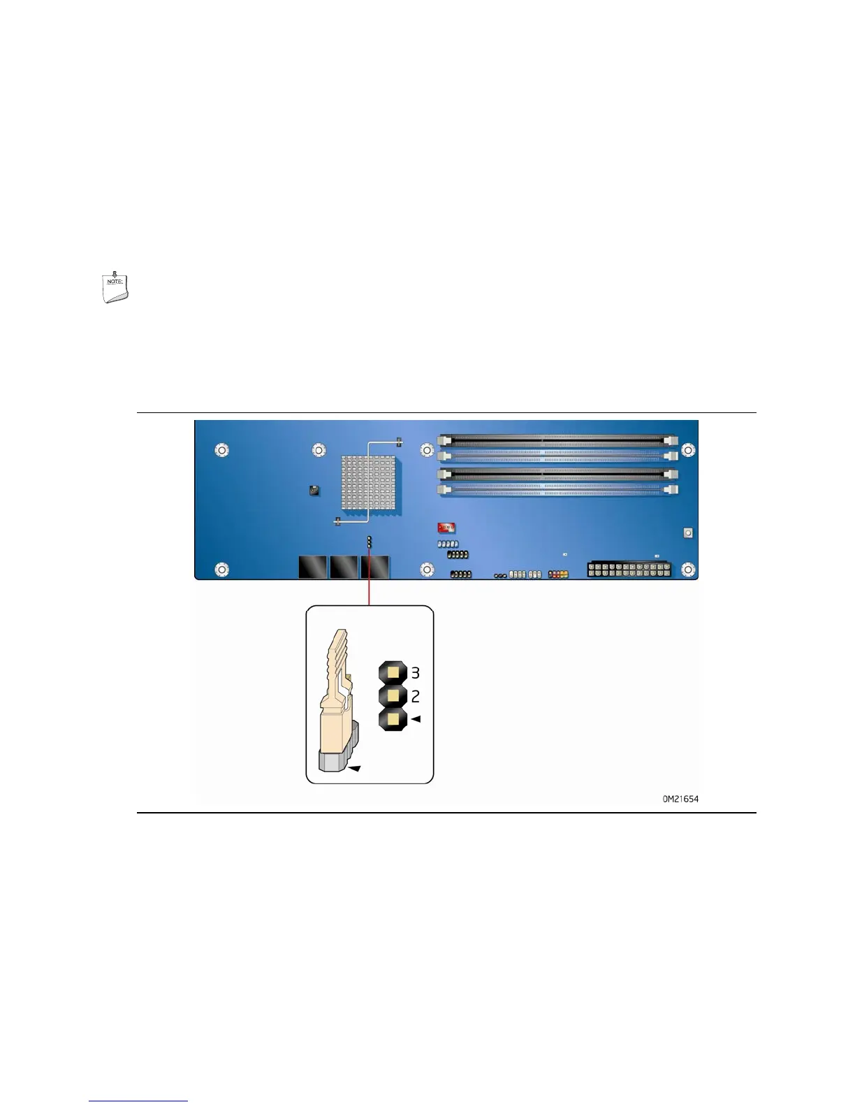
Figure 31 shows the location of the Desktop Board’s BIOS confi
guration jumper block.
Figure 31. Location of the BIOS Configuration Jumper Block
The three-pin BIOS jumper block enables board configuration to be done in the BIOS
Setup program. Table 13 shows the jumper settings
for the BIOS Setup program
modes.