Intel Desktop Board D945PLRN Technical Product Specification
46
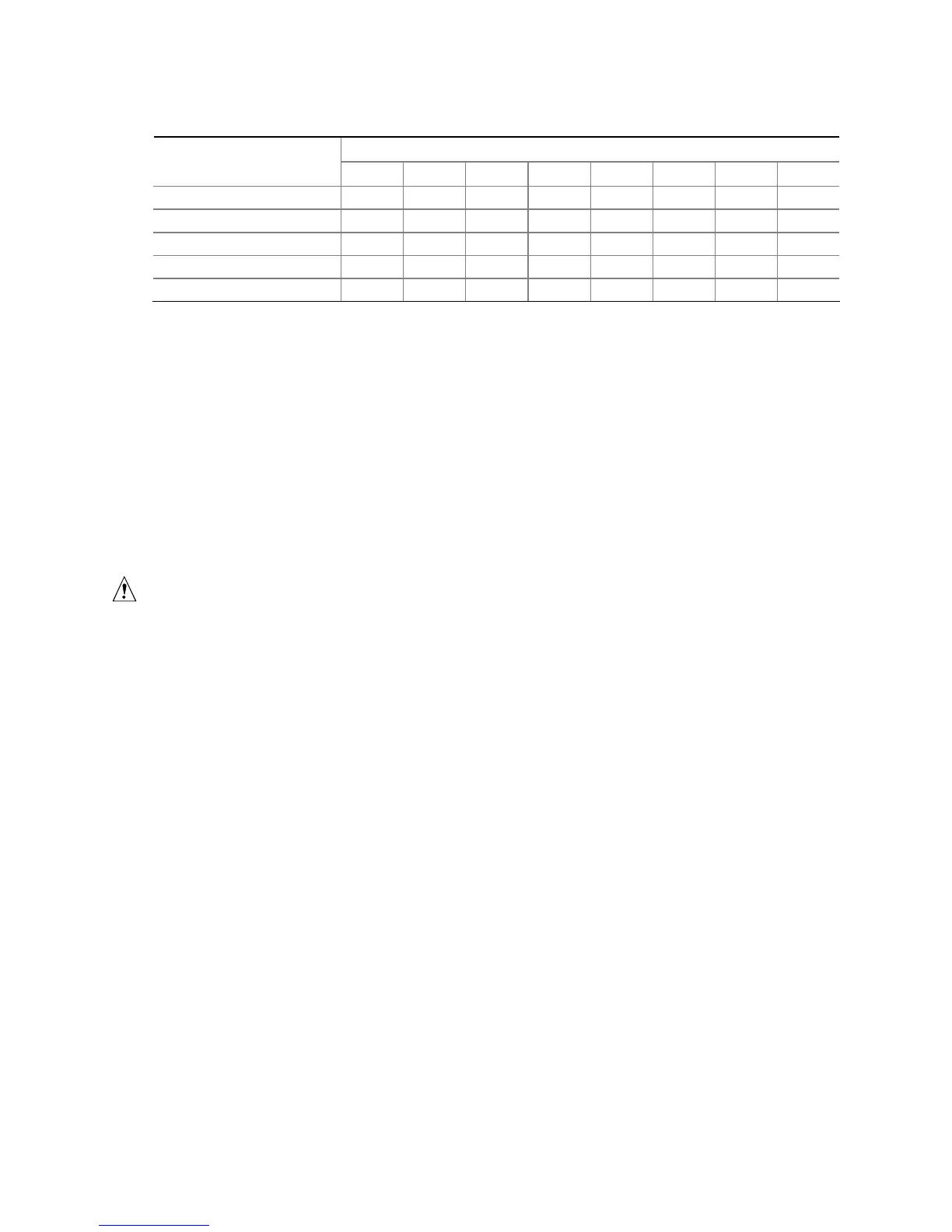
Table 14. PCI Interrupt Routing Map
ICH7 PIRQ Signal Name
PCI Interrupt Source
PIRQA PIRQB PIRQC PIRQD PIRQE PIRQF PIRQG PIRQH
ICH7 LAN INTA
PCI bus connector 1 INTD INTA INTB INTC
PCI bus connector 2 INTC INTB INTA INTD
PCI bus connector 3 INTD INTC INTA INTB
PCI bus connector 4 INTB INTA INTC INTD
NOTE
In PIC mode, the ICH7 can connect each PIRQ line internally to one of the IRQ signals (3, 4, 5, 6,
7, 9, 10, 11, 12, 14, and 15). Typically, a device that does not share a PIRQ line will have a unique
interrupt. However, in certain interrupt-constrained situations, it is possible for two or more of the
PIRQ lines to be connected to the same IRQ signal. Refer to Table 12 for the allocation of PIRQ
lines to IRQ signals in APIC mode.
PCI interrupt assignments to the USB ports, Serial ATA ports, and PCI Express ports are dynamic.
2.7 Connectors
CAUTION
Only the following connectors have overcurrent protection: back panel USB, front panel USB, and
PS/2.
The other internal connectors are not overcurrent protected and should connect only to devices
inside the computer’s chassis, such as fans and internal peripherals. Do not use these connectors
to power devices external to the computer’s chassis. A fault in the load presented by the external
devices could cause damage to the computer, the power cable, and the external devices themselves.
This section describes the board’s connectors. The connectors can be divided into these groups:
• Back panel I/O connectors (see page 47)
• Component-side I/O connectors (see page 48)