Installing and Replacing Desktop Board Components
45
Connecting to the Alternate Front Panel Power LED
Header
Figure 20, C on page 42 shows the location of the alternate front panel power LED
header. Pins 1 and 3 of this header duplicate the signals on pins 2 and 4 of the front
panel header. If your chassis has a three-pin power LED cable, connect it to this
header.
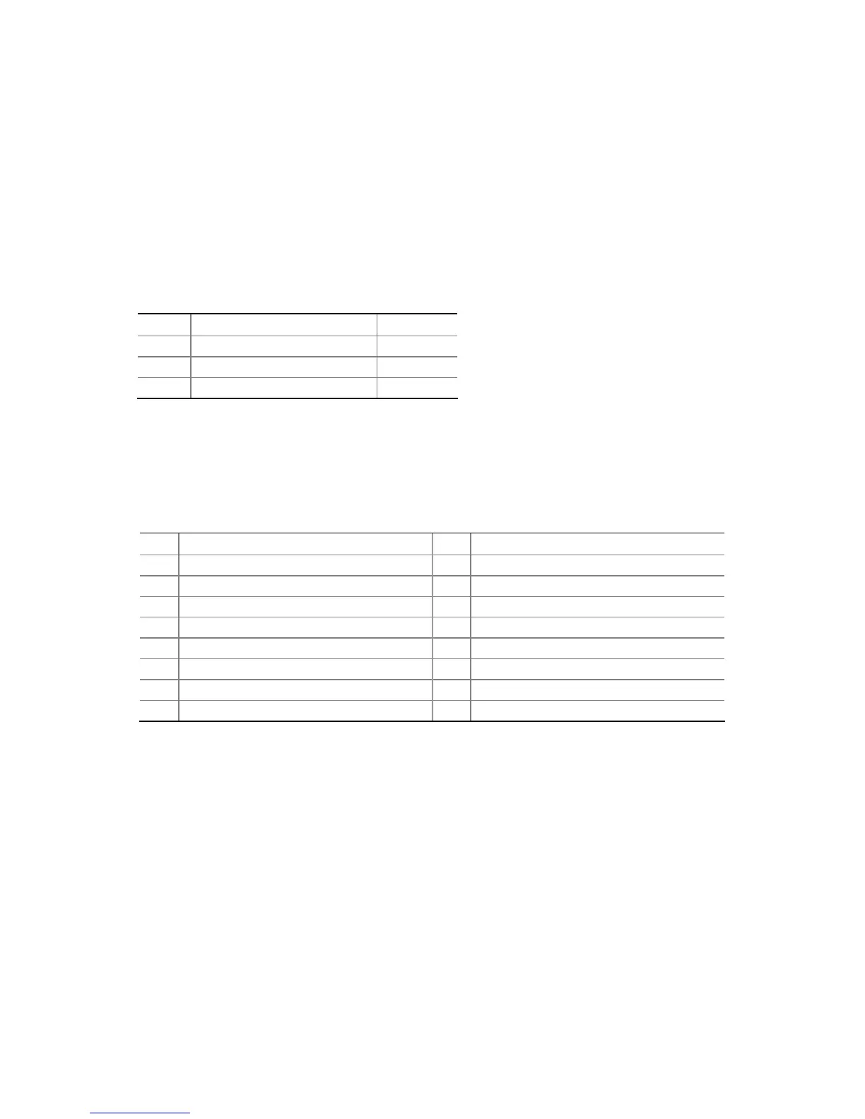
Table 8 shows the pin assignments for the front panel header.
Table 8. Alternate Front Panel Power LED Header
Pin Description In/Out
1 Front panel green LED Out
2 No pin
3 Front panel yellow LED Out
Connecting to the HD Audio Link Header
See Figure 20, A for the location of the HD Audio Link header. Table 9 shows the pin
assignments for the header.
Table 9. HD Audio Link Header Signal Names
Pin Signal Name Pin
Signal Name
1 BLCK 2 Ground
3 RST 4 3.3V/1.5V I/O
5 SYNC 6 Ground
7 SDO 8 3.3V_CORE
9 SDI 10 +12V
11 No connection 12 Key (no pin)
13 No connection 14 3.3V/1.5V STBY
15 No connection 16 Ground
 Loading...