Intel Desktop Board DN2800MT Product Guide
30
S/PDIF Header
Figure 11, A shows the location of the S/PDIF output header. Table 13 shows the pin
assignments and signal names for the S/PDIF output header.
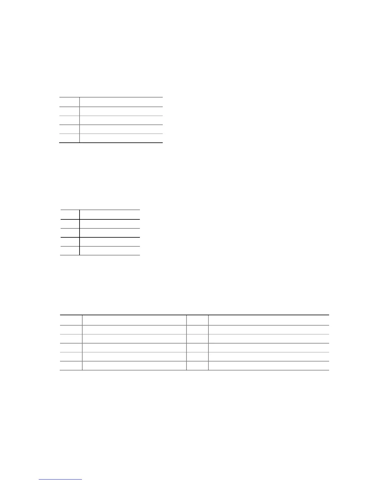
Table 4. S/PDIF Header Signal Names
Pin Description
1 Ground
2 S/PDIF Out
3 Key (no pin)
Internal Stereo Speakers Connector
Figure 11, B shows the location of the internal stereo speakers connector and Table 5
shows the pin assignments and signal names.
Table 5. Internal Stereo Speakers
Connector Signal Names
Pin Signal Name
1 Front_L−
2 Front_L+
3 Front_R+
Serial Port Headers
Figure 11, C shows the location of the serial port headers. Table 6 shows the pin
assignments and signal names for each serial port header.
Table 6. Serial Port Header
Pin Signal Name Pin Signal Name
1 DCD (Data Carrier Detect) 2 RXD# (Receive Data)
3 TXD# (Transmit Data) 4 DTR (Data Terminal Ready)
5 Ground 6 DSR (Data Set Ready)
9 RI (Ring Indicator) 10 Key (no pin)