Installing and Replacing Desktop Board Components
31
Parallel Port Header
Figure 11, D shows the location of the parallel port header. Table 7 shows the pin
assignments and signal names for the parallel port header.
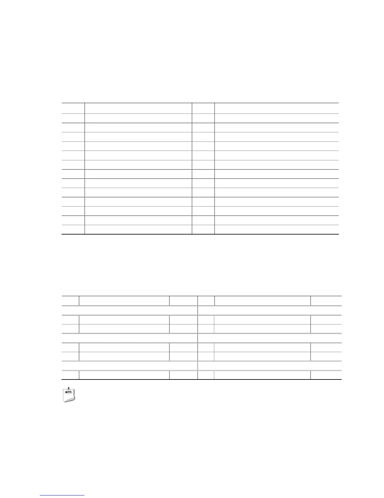
Table 7. Parallel Port Header
Pin Signal Name Pin Signal Name
3 PD0 4 PERROR
5 PD1 6 INT#
7 PD2 8 SLCTIN#
11 PD4 12 Ground
13 PD5 14 Ground
15 PD6 16 Ground
21 BUSY 22 Ground
23 FAULT# 24 Ground
Front Panel Header
Figure 11, E shows the location of the front panel header. Table 8 shows the pin
assignments and signal names for the front panel header.
Table 8. Front Panel Header Signal Names
Pin Description In/Out Pin Description In/Out
Hard Drive Activity LED Power LED
1 Hard disk LED pull-up to +5 V Out 2 Front panel LED+ Out
5 Ground 6 Power switch In
Power Not Connected
9 Power (+5 V DC) Out 10 No pin
NOTE
When connecting individual wires from your chassis front panel to the front panel
header, be sure to observe the connection polarity. Positive wires are usually
solid color and negative wires are usually white or striped.