Installing and Replacing Desktop Board Components
33
Front Panel USB 2.0 Header (with Flash Drive Support)
Figure 11, H shows the location of the standard front panel dual-port USB 2.0 header
and Table 12 shows the pin assignments and signal names.
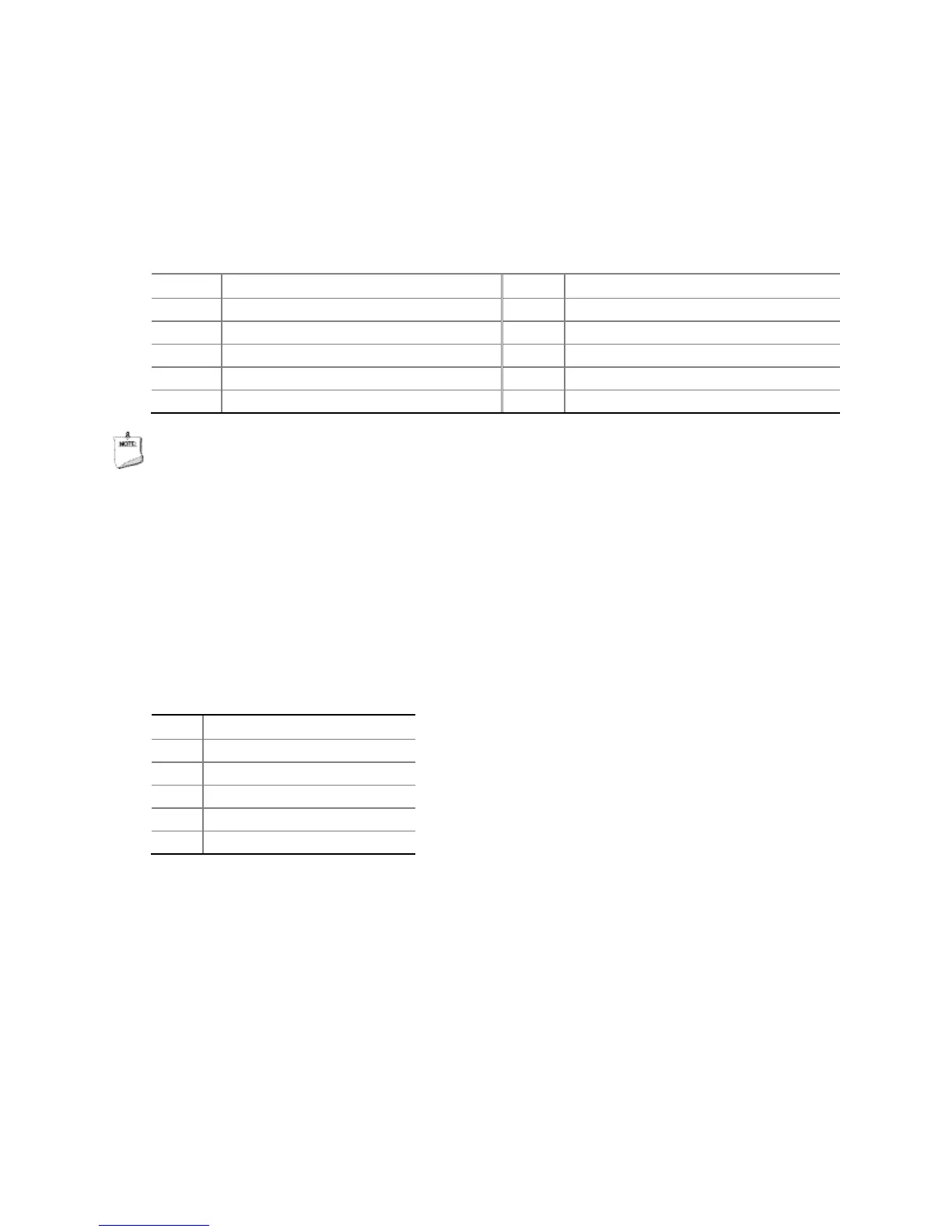
Table 12. Front Panel Dual-Port USB 2.0 Header (with Flash Drive Support)
Signal Names
Pin Signal Name Pin Signal Name
1 Power (+5 V) 2 Power (+5 V)
3 D- 4 D-
5 D+ 6 D+
NOTE
Computer systems that have an unshielded cable attached to a USB port might not
meet FCC Class B requirements, even if no device or a low-speed USB device is
attached to the cable. Use a shielded cable that meets the requirements for a
full-speed USB device.
DMIC Header
Figure 11, I shows the location of the DMIC header. Table 13 shows the pin
assignments and signal names for the DMIC header.
Table 13. DMIC Header Signal Names
Pin Description
1 3.3 V
4 DMIC_CLK
5 Key (no pin)