Technical Reference
47
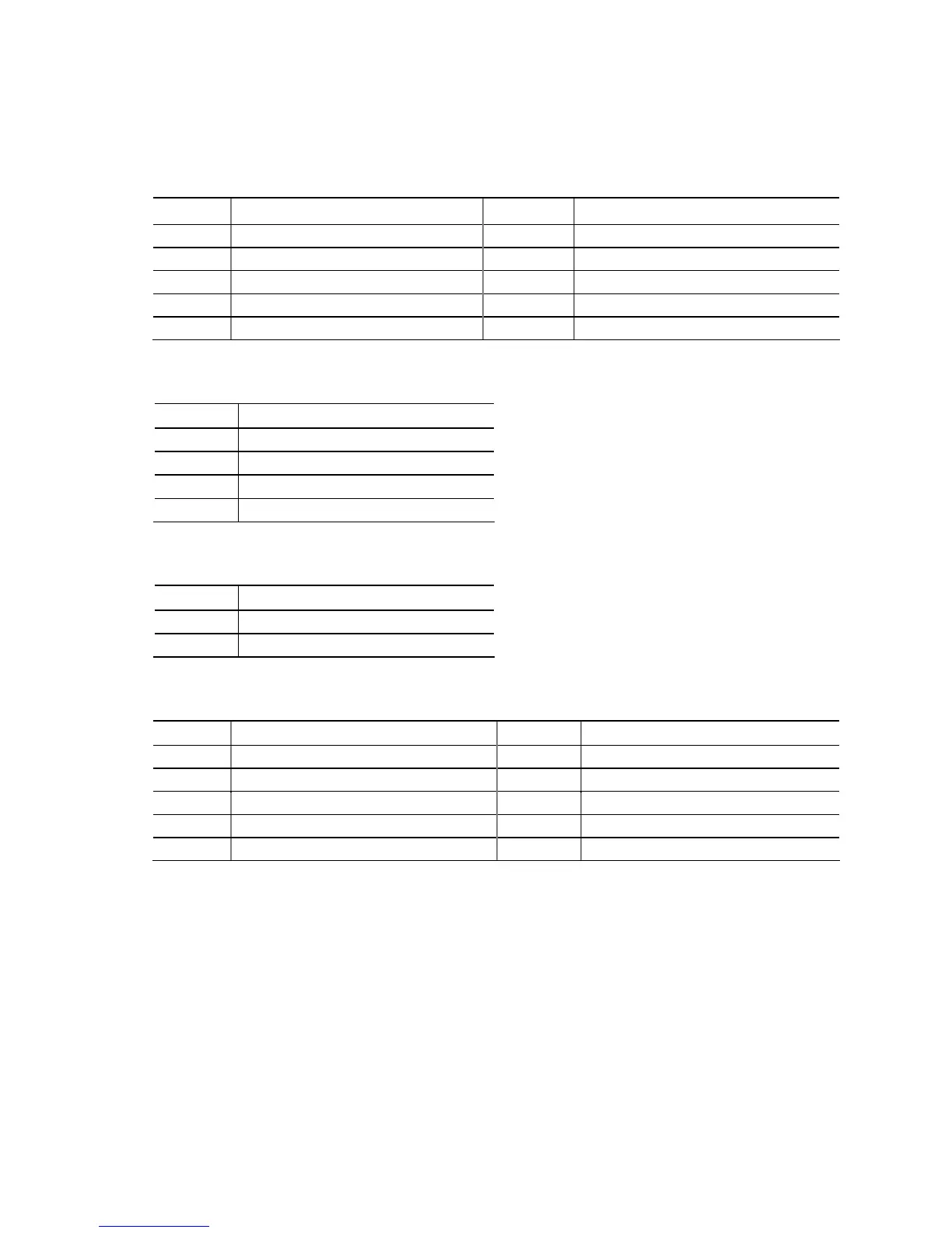
2.2.2.1 Signal Tables for the Connectors and Headers
Table 10. Serial Port Header
Pin Signal Name Pin Signal Name
1 DCD (Data Carrier Detect) 2 RXD# (Receive Data)
3 TXD# (Transmit Data) 4 DTR (Data Terminal Ready)
5 Ground 6 DSR (Data Set Ready)
7 RTS (Request To Send) 8 CTS (Clear To Send)
9 RI (Ring Indicator) 10 Key (no pin)
Table 11. S/PDIF Header
Pin Signal Name
1 Ground
2 S/PDIF out
3 Key (no pin)
3 +5V_DC
Table 12. Internal Mono Speaker Header
Pin Signal Name
1 −
2 +
Table 13. Front Panel Audio Header for Intel HD Audio
Pin Signal Name Pin Signal Name
1 [Port 1] Left channel 2 Ground
3 [Port 1] Right channel 4 PRESENCE# (Dongle present)
5 [Port 2] Right channel 6 [Port 1] SENSE_RETURN
7 SENSE_SEND (Jack detection) 8 Key (no pin)
9 [Port 2] Left channel 10 [Port 2] SENSE_RETURN