Intel
®
Server Board S5500BC TPS Connector / Header Locations and Pin-outs
Revision 1.0 Intel order number: E42249-003 57
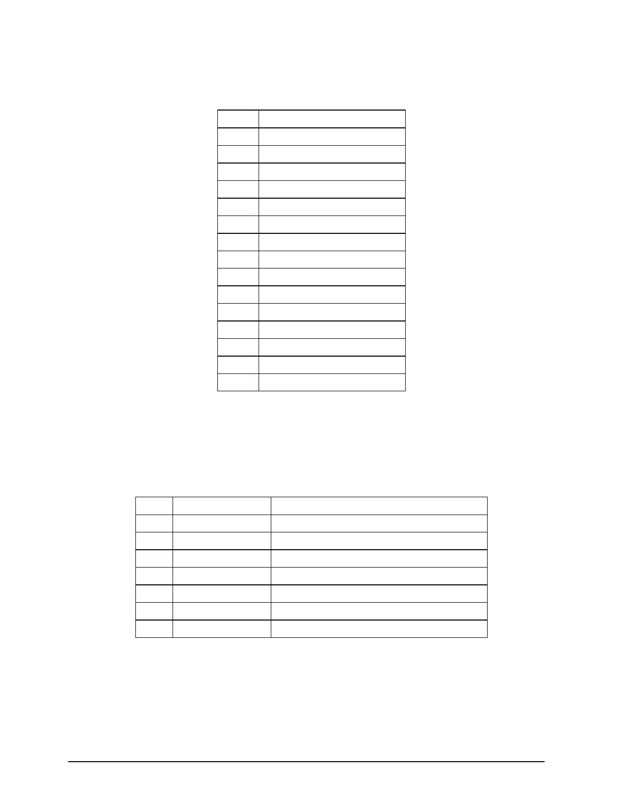
Table 17. VGA Connector Pin-out (J7A1)
Pin Signal Name
1 VGA_RED
2 VGA_GREEN
3 VGA_BLUE
4 RESERVED
5 GND
6 GND
7 GND
8 GND
9 5V
10 GND
11 RESERVED
12 DDCDAT
13 HSYNC
14 VSYNC
15 DDCCLK
5.6.2 SATA II Connectors
The Intel
®
Server Board S5500BC provides six Serial ATA connectors (J1B4, J1B3, J1A2, J1B1,
J1B2, and J2B1).
Table 18. SATA Connector Pin-out (J1B4, J1B3, J1A2, J1B1, J1B2, and J2B1)
Pin Signal Name Description
1 GND GND1
2 SATA#_TX_P_C Positive side of transmit differential pair
3 SATA#_TX_N_C Negative side of transmit differential pair
4 GND GND2
5 SATA#_RX_N_C Negative side of Receive differential pair
6 SATA#_RX_P_C Positive side of Receive differential pair
7 GND GND3