Intel
®
Server Board S5500BC TPS List of Figures
Revision 1.0 Intel order number: E42249-003 ix
List of Figures
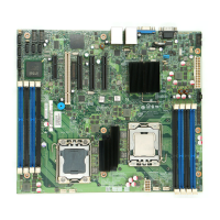
Figure 1. Intel
®
Server Board S5500BC picture......................................................... 4
Figure 2. Intel
®
Server Board S5500BC Layout......................................................... 5
Figure 3. Key Connector and LED Indicator Identification......................................... 6
Figure 4. Mounting hole location................................................................................ 7
Figure 5. Major connector pin-1 locations.................................................................. 8
Figure 6. S5500BC Board Primary Side Keepouts.................................................... 9
Figure 7. S5500BC Board PRIMARY SIDE CARD-SIDE KEEPOUT ZONE ........... 10
Figure 8. Secondary Side Keepout -- Mounting Hole Keepout................................ 11
Figure 9. Secondary Side Keepout - CPU Socket and Rubber Pad Keepout.......... 12
Figure 10. Intel
®
Light-Guided Diagnostic LED Locations ....................................... 13
Figure 11. External I/O Layout................................................................................ 14
Figure 12. Functional Block Diagram....................................................................... 15
Figure 13. Intel
®
IOH 5500 Chipset with Intel
®
QuickPath Interconnect Block
Diagram ................................................................................................................... 17
Figure 14. ILM backplate and URS.......................................................................... 22
Figure 15. DIMM Organization................................................................................. 23
Figure 16. Channel slots Configuration ................................................................... 24
Figure 17. Integrated BMC Block Diagram .............................................................. 39
Figure 18. SMBUS Block Diagram .......................................................................... 43
Figure 19. Jumper Blocks ........................................................................................ 63
Figure 20. Power Distribution Block Diagram .......................................................... 69
Figure 21. Output Voltage Timing............................................................................ 74
Figure 22. Turn On/Off Timing (Power Supply Signals)........................................... 75
Figure 23. Diagnostic LED Placement Diagram ...................................................... 99
Figure 24. 1U Intel
®
Server System SR1630BC Overview .................................... 103
Figure 25. 5U Intel
®
Entry Server Chassis SC5650 Overview .............................. 104