Installing and Replacing Desktop Board Components
47
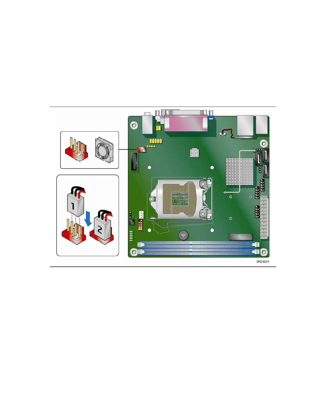
Connecting System Fan and Power Supply
Cables
Connecting a System Fan Cable
Connect system fan cables to the system fan header on the Desktop Board. Figure 21
shows the location of the system fan header.
Figure 21. Location of the System Fan Header