Installing and Replacing Desktop Board Components
51
8. Use the arrow keys to select Clear Passwords. Press <Enter> and Setup displays a
pop-up screen requesting that you confirm clearing the password. Select Yes and
press <Enter>. Setup displays the maintenance menu again.
9. Press <F10> to save the current values and exit Setup.
10. Turn off the computer. Disconnect the computer’s power cord from the AC power
source.
11. Remove the computer cover.
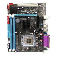
12. To restore normal operation, place the jumper on pins 1-2 as shown below.
13. Replace the cover, plug in the computer, and turn on the computer.
Replacing the Battery
A coin-cell battery (CR2032) powers the real-time clock and CMOS memory. When
the computer is not plugged into a wall socket, the battery has an estimated life of
three years. When the computer is plugged in, the standby current from the power
supply extends the life of the battery. The clock is accurate to ± 13 minutes/year at
25 ºC with 3.3 VSB applied.
When the voltage drops below a certain level, the BIOS Setup program settings stored
in CMOS RAM (for example, the date and time) might not be accurate. Replace the
battery with an equivalent one. Figure 24 on page 56 shows the location of the
battery.
CAUTION
Risk of explosion if the battery is replaced with an incorrect type. Batteries should be
recycled where possible. Disposal of used batteries must be in accordance with local
environmental regulations.
PRÉCAUTION
Risque d'explosion si la pile usagée est remplacée par une pile de type incorrect. Les
piles usagées doivent être recyclées dans la mesure du possible. La mise au rebut des
piles usagées doit respecter les réglementations locales en vigueur en matière de
protection de l'environnement.
FORHOLDSREGEL
Eksplosionsfare, hvis batteriet erstattes med et batteri af en forkert type. Batterier
bør om muligt genbruges. Bortskaffelse af brugte batterier bør foregå i
overensstemmelse med gældende miljølovgivning.