7
Chapter 3
Connectors, Headers & Jumpers Setting
3-1 Connectors
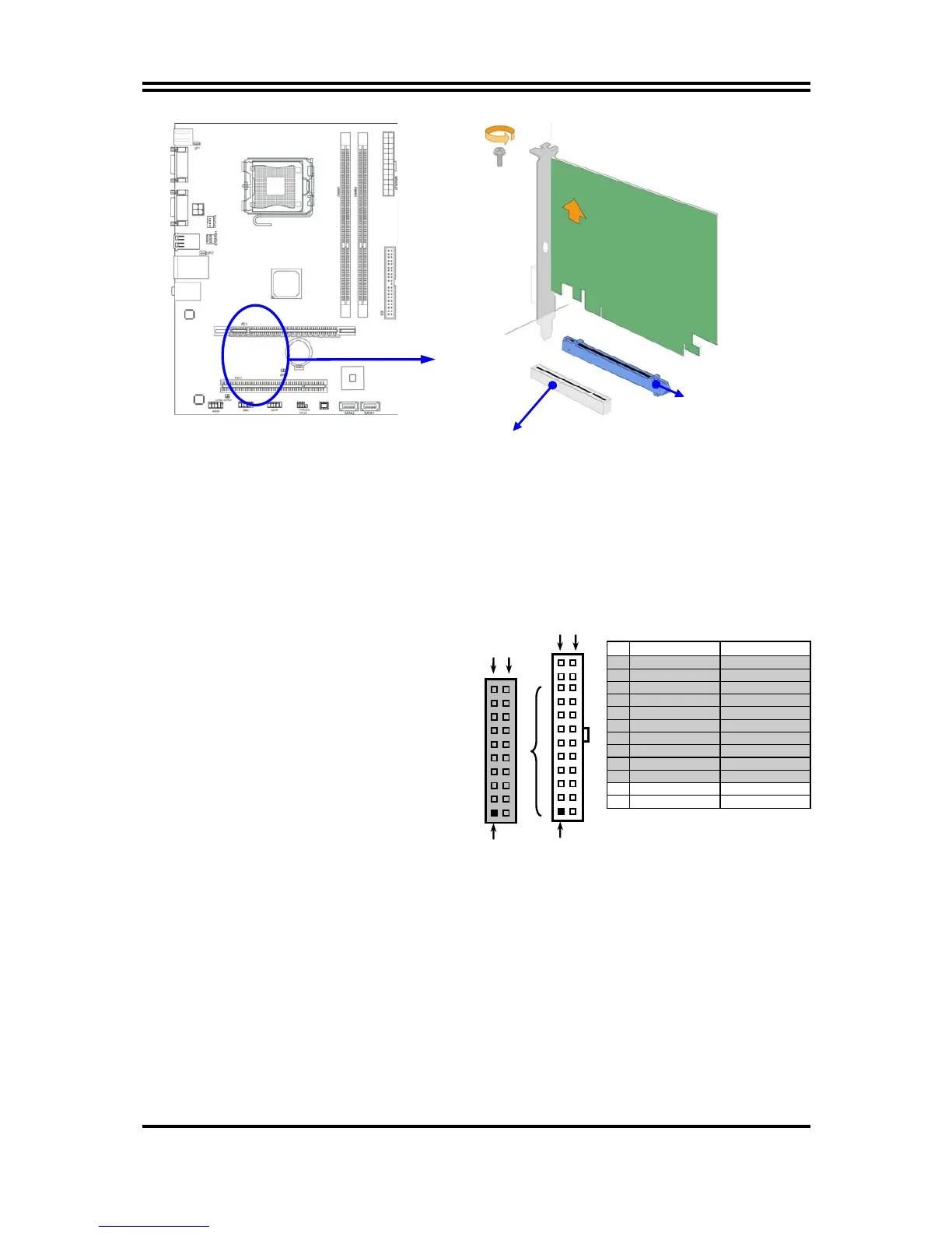
(1) Power Connector (24-pin block): ATXPWR
ATX Power Supply connector:
This is a new defined 24-pins
connector that usually comes
with ATX case. The ATX Power
Supply allows using soft power
on momentary switch that
connect from the front panel
switch to 2-pins Power On jumper
pole on the motherboard. When
the power switch on the back of
the ATX power supply turned on,
the full power will not come into
the system board until the front
panel switch is momentarily
pressed. Press this switch again will turn off the power to the system board.
** We recommend that you use an ATX 12V Specification 2.0-compliant power
supply unit (PSU) with a minimum of 350W power rating. This type has 24-pin
and 4-pin power plugs.
** If you intend to use a PSU with 20-pin and 4-pin power plugs, make sure that the
20-pin power plug can provide at least 15A on +12V and the power supply unit
has a minimum power rating of 350W. The system may become unstable or may
not boot up if the power is inadequate.
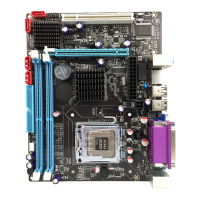
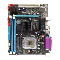
PE1 / PCI-E x16 Slot
32-bit PCI Slot
Pin 1
ROW1 ROW2
24-Pin
ROW1 ROW2
Pin 1
20-Pin
PIN ROW1 ROW2
1 3.3V 3.3V
2 3.3V -12V
3 GND GND
4 5V Soft Power On
5 GND GND
6 5V GND
7 GND GND
8 Power OK -5V
9 +5V (for Soft Logic) +5V
10 +12V +5V
11 +12V +5V
12 +3V GND