EasyManua.ls Logo

Intel H61 - Header Pin Definitions

Intel H61
37 pages
Print Icon
To Next Page IconTo Next Page
To Previous Page IconTo Previous Page
Loading...
12
*The above diagram for illustration is from model NLB75.
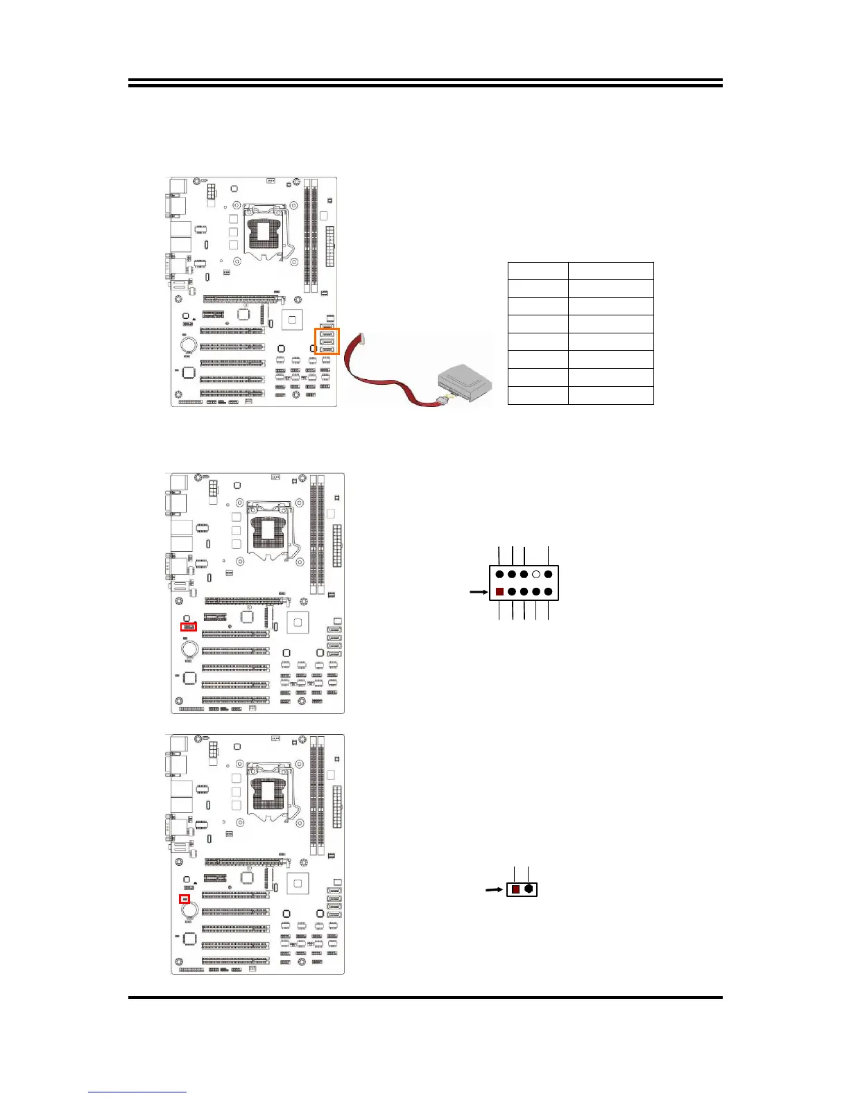
(4) SATA2/3/4: SATAII Port connector
These connectors are high-speed SATAII ports that support 3GB/s transfer rate.
Pin No. Definition
1 GND
2 TXP
3 TXN
4 GND
5 RXN
6 RXP
7 GND
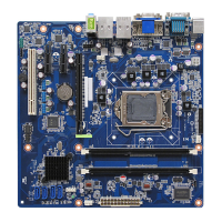
2-2-3 Header Pin Definition
(1) FP_AUDIO (9-pin): Line-Out, MIC-In Header
This header is connected to Front Panel Line-out, MIC connector with cable.
Line-Out, MIC Header
FP_AUDIO
Pin 1
MIC1-R
LINE OUT-L
MIC
1
-
L
LINE OUT-R
NC
GND
NC
NC
NC
2
(2) HDMI_SPDIF (2-pin): HDMI-SPDIF Out header
HDMI_SPDIF Header
Pin
1
SPDIF
GND

Related product manuals