Motherboard Description
33
Table 2. ISA Bus Connectors (continued)
Pin Signal Name Pin Signal Name
D4 IRQ11 C4 LA21
D5 IRQ12 C5 LA20
D6 IRQ15 C6 LA19
D7 IRQ14 C7 LA18
D8 DACK0# C8 LA17
D9 DRQ0 C9 MEMR# (MRDC#)
D10 DACK5# C10 MEMW# (MWTC#)
D11 DRQ5 C11 SD8
D12 DACK6# C12 SD9
D13 DRQ6 C13 SD10
D14 DACK7# C14 SD11
D15 DRQ7 C15 SD12
D16 +5 V C16 SD13
D17 Master16# (MASTER#) C17 SD14
D18 Ground C18 SD15
Note: Items in parentheses are alternate versions of signal names
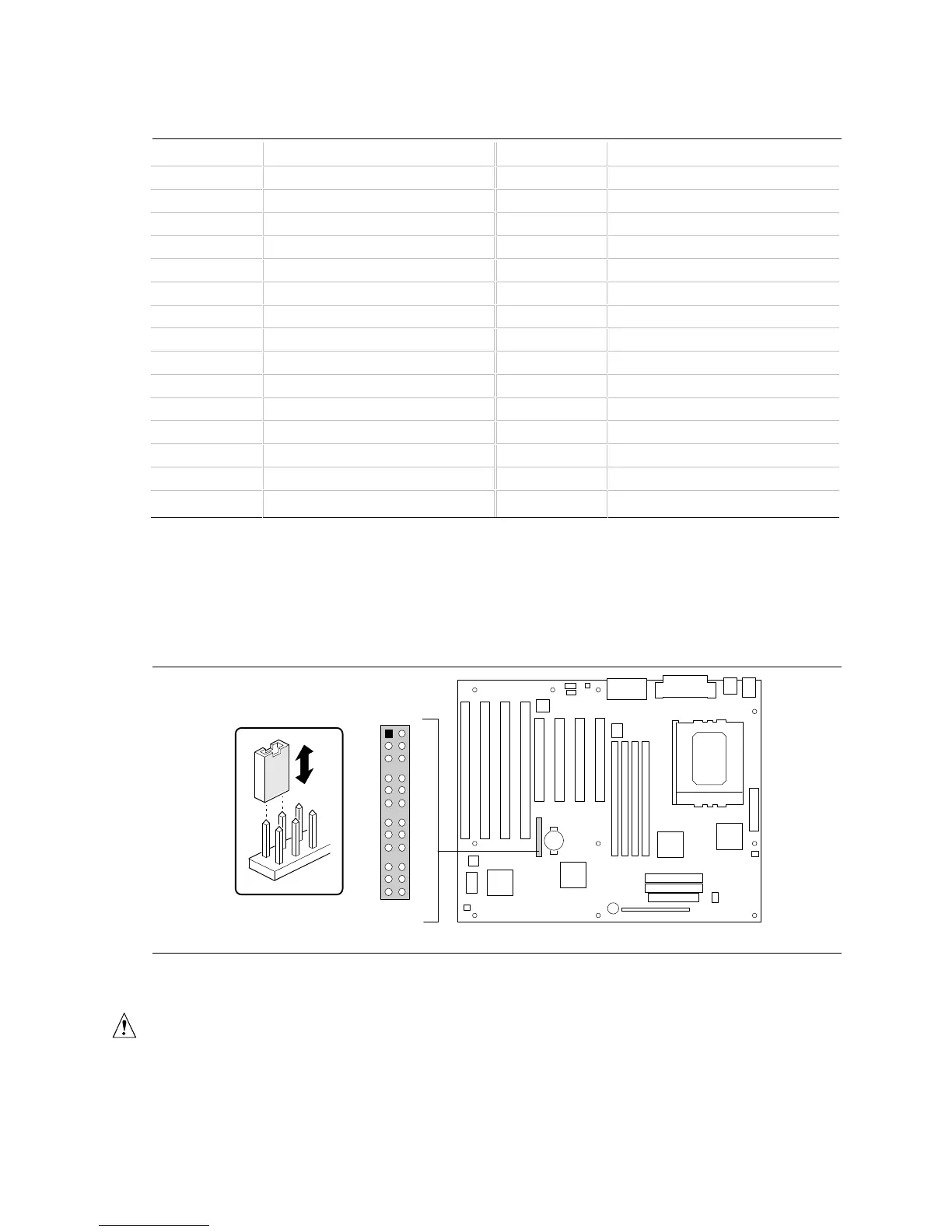
1.13 Jumper Settings
Figure 7 shows the location of jumper blocks on the motherboard.
OM05525
30
22
14
6
29
21
5
13
26
25
1817
10
9
2
1
J6D1
Figure 7. Jumper Locations
CAUTION
Do not move any of the jumpers with the power on. Always turn off the power and unplug the
power cord from the computer before changing jumpers.