11Intenza Treadmills Handbook. 550Ti and 450Ti2&Ti2S Assembly Instructions
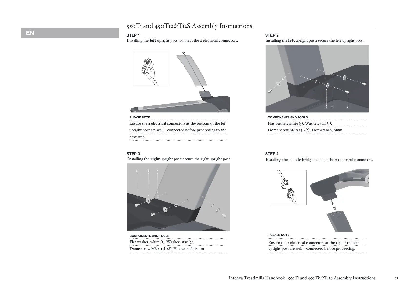
550Ti and 450Ti2&Ti2S Assembly Instructions
STEP 1
Installing the left upright post: connect the 2 electrical connectors.
STEP 2
Installing the left upright post: secure the left upright post.
PLEASE NOTE
Ensure the 2 electrical connectors at the bottom of the left
upright post are well—connected before proceeding to the
next step.
. ... .... ..... ........... ..... ............... ..... ....... ..... ... ... . . ................... .
. ... .... ..... ........... ..... ............... ..... ....... ..... ... ... . . ................... .
. ... .... ..... ........... ..... ............... ..... ....... ..... ... ... . . ................... .
. ... .... ..... ........... ..... ............... ..... ....... ..... ... ... . . ................... .
COMPONENTS AND TOOLS
Flat washer, white (5), Washer, star (7),
Dome screw M8 x 15L (8), Hex wrench, 6mm
. . ... . ... ........ ....... ... . ... ... . . ... ... ... . ... ....... ... . ... ... ... . ..... ... ..... ... ...
. . ... . ... ........ ....... ... . ... ... . . ... ... ... . ... ....... ... . ... ... ... . ..... ... ..... ... ...
. . ... . ... ........ ....... ... . ... ... . . ... ... ... . ... ....... ... . ... ... ... . ..... ... ..... ... ...
. ... .... ..... ........... ..... ............... ..... ....... ..... ... ... . . ................... .
. ... .... ..... ........... ..... ............... ..... ....... ..... ... ... . . ................... .
. ... .... ..... ........... ..... ............... ..... ....... ..... ... ... . . ................... .
STEP 4
Installing the right upright post: secure the right upright post.
COMPONENTS AND TOOLS
Flat washer, white (5), Washer, star (7),
Dome screw M8 x 15L (8), Hex wrench, 6mm
. . ... . ... ........ ....... ... . ... ... . . ... ... ... . ... ....... ... . ... ... ... . ..... ... ..... ... ...
. . ... . ... ........ ....... ... . ... ... . . ... ... ... . ... ....... ... . ... ... ... . ..... ... ..... ... ...
. . ... . ... ........ ....... ... . ... ... . . ... ... ... . ... ....... ... . ... ... ... . ..... ... ..... ... ...
STEP 3
7 85
8 5 7
Installing the console bridge: connect the 2 electrical connectors.
PLEASE NOTE
Ensure the 2 electrical connectors at the top of the left
upright post are well—connected before proceeding.
EN
 Loading...