1
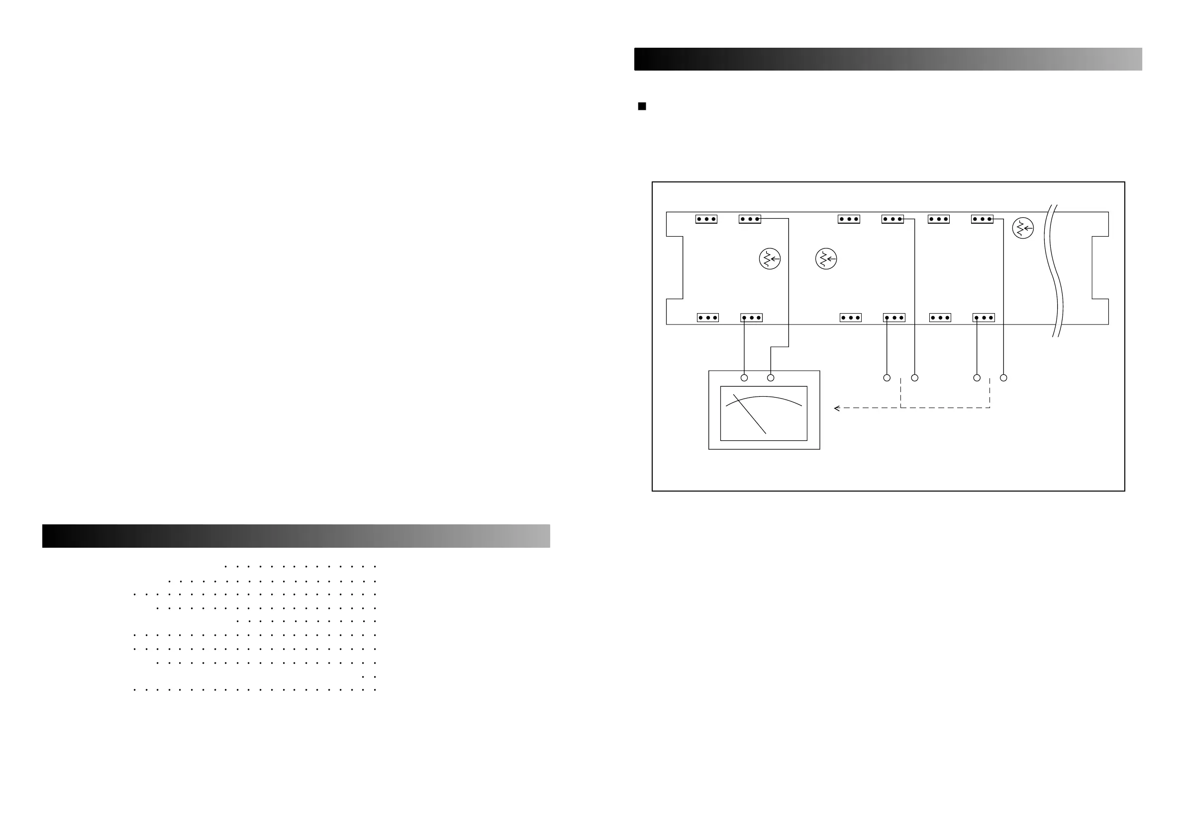
IDLE CURRENT
A. Setting
Set the mixer master volume minimum.
B. Connection
C. Adjustment
Adjust VR101, so that the voltage through the between emitter of Q115 and Q116 become 5mV~6mV.
Adjust VR201, so that the voltage through the between emitter of Q215 and Q216 become 5mV~6mV.
Adjust VR301, so that the voltage through the between emitter of Q315 and Q316 become 5mV~6mV.
ELECTRICAL ADJUSTMENT PROCEDURE
Electrical Adjustment Procedure 1
Surround Processor 3 2, 3, 4, 5, 6
Specifications
7
Electrical Parts List
8, 9, 10, 11, 12, 13, 14, 15, 16, 17
Top and Bottom View of P.C. Board
18, 19, 20
Wiring Diagram 21
Block Diagram 22
Schematic Diagram
23, 24, 25, 26, 27, 28
Exploded View of Cabinet & Chassis / Mechanical Parts List
29, 30
Ass’y Drawing 31, 32
CONTENTS