BSC4 Operating Manual
Interface Inc. ● 7401 East Butherus Drive, Scottsdale, Arizona 85260 USA ● Phone 480.948.5555 ● Fax 480.948.1924
www.interfaceforce.com ● Email: contact@interfaceforce.com ● 800.947.5598
Document Number 15-183 Rev B Page 20 of 74
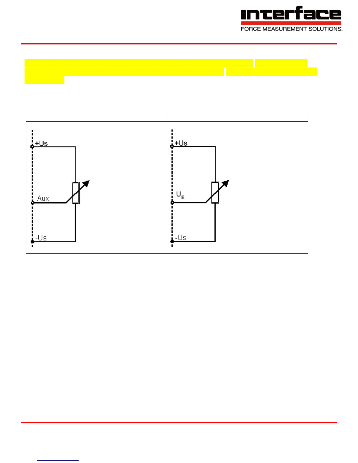
Wiring Diagram for Position Sensors
The measuring amplifier must be configured by the manufacturer separately when using it with
potentiometric position sensors (linear potentiometers or draw wire displacement sensors) for the
M12 version.
Th
e
p
o
s
i
t
io
n
s
ens
o
r
’
s
w
iper
is
co
nnec
t
ed
t
o
t
h
e
m
ea
s
ur
ing
a
m
p
li
f
ier
’
s
“
Aux
”
inp
ut
(
M
12
)
o
r
“U
E
“
(SubD37). The position sensor supplies via the sensor supply +Us and -Us.
The potentiometric position sensor is supplied with 2.5 V. The “Aux”
input or U
E
records voltages of 0...5 V.