BSC4 Operating Manual
Interface Inc. ● 7401 East Butherus Drive, Scottsdale, Arizona 85260 USA ● Phone 480.948.5555 ● Fax 480.948.1924
www.interfaceforce.com ● Email: contact@interfaceforce.com ● 800.947.5598
Document Number 15-183 Rev B Page 66 of 74
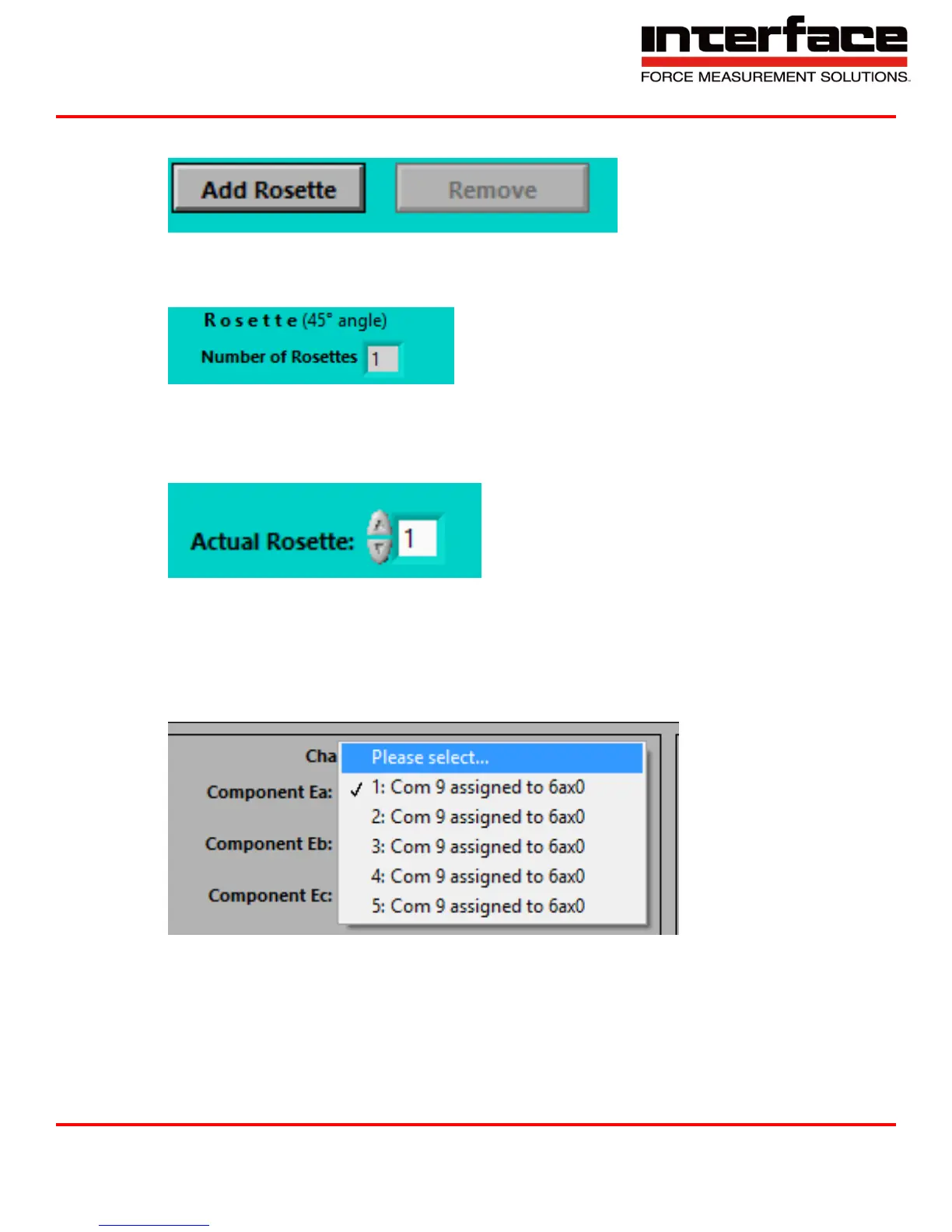
4. Add Rosette / Remove
FIGURE 91 - ADD ROSETTE
5. Number of Rosettes – Number of included rosette strain gauges which are configured already.
FIGURE 92 - NUMBER OF ROSETTES
6. Actual Rosette – If you have configured more than one rosette strain gauge, here you can switch
between the different rosette stain gauge settings.
FIGURE 93 - ACTUAL ROSETTE
7. Component Ea: - The Rosette-Strain gauge consists of three single strain gauges which are
arranged at an angle of 45° to each other. Choose here for the physical channel of your
measuring amplifier where the single strain gauge Epsilon A is connected to. The resulting angle
value of Phi refers to the longitudinal axis of this single strain gauge.
FIGURE 94 - COMPONENT EA