EasyManuals Logo

Interface TS14 User Manual

Default Icon
11 pages
To Next Page IconTo Next Page
To Previous Page IconTo Previous Page
Page #7 background imageLoading...
Page #7 background image
E-Mail: keiths@interfaceforce.com
Technical changes reserved
TS Series Reaction Torque.doc
Internet: www.interfaceforce.com
Page 7 of 11
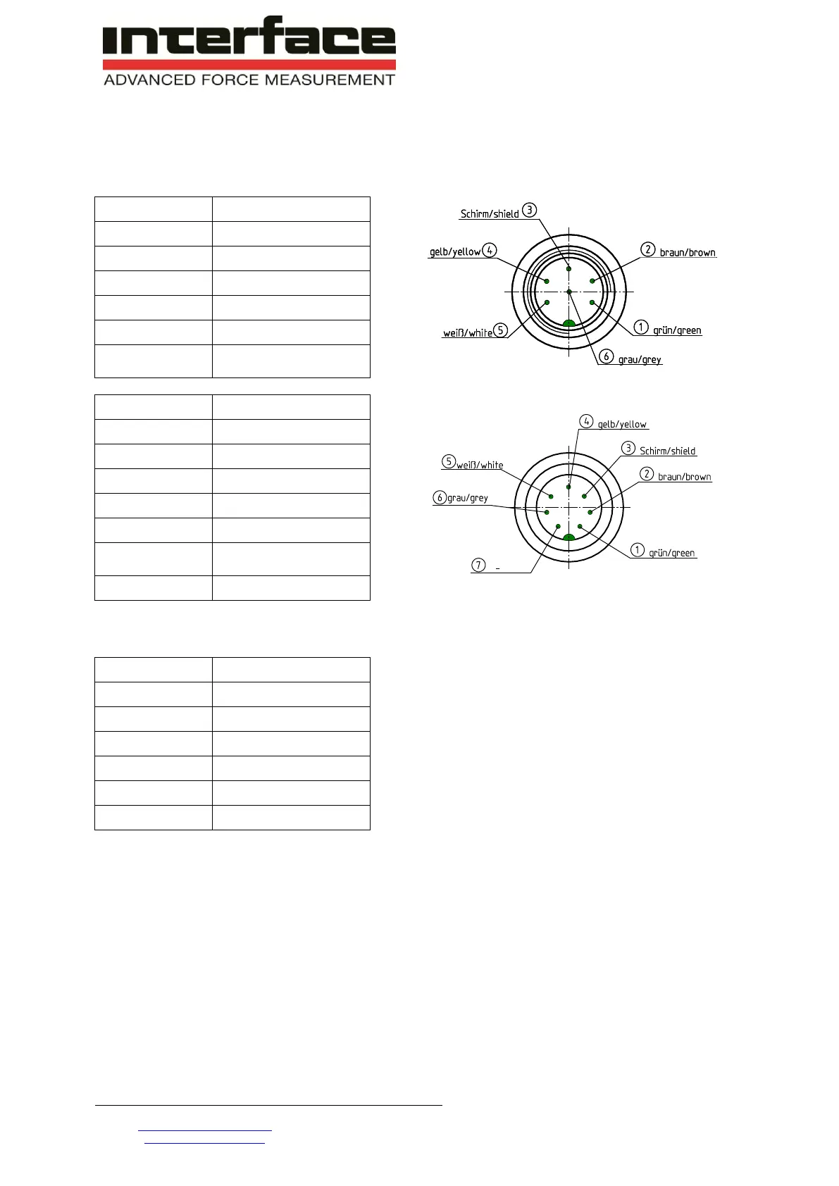
5 Electrical Connection
5.1 Pin Connection
6-pin
Function
1
SG- excitation -
2
SG- excitation +
3
Shield
4
SG- signal +
5
SG- signal -
6
100% calibration
control
7-pin
Function
1
SG- excitation -
2
SG- excitation +
3
Shield
4
SG- signal +
5
SG- signal -
6
100% calibration
control
7
-
View: socket on soldering side
5.2 Free Cable Ends
Wire
Function
green
Excitation (-)
brown
Excitation (+)
yellow
Signal (+)
white
Signal (-)
grey
Control
netting
Shield
5.3 Cable
Only use a shielded cable with preferably small capacity. We recommend measuring cables from our
product range. They have been tested in combination with our sensors and meet the metrological
requirements.
5.4 Shielding Connection
In combination with the sensor and the external electronics, the shield forms a Faraday Cage. By this,
electro-magnetic disturbances do not have any influence on the measurement signal.
At potential difference problems we recommend to ground the sensor.

Questions and Answers:

Question and Answer IconNeed help?

Do you have a question about the Interface TS14 and is the answer not in the manual?

Interface TS14 Specifications

General IconGeneral
BrandInterface
ModelTS14
CategorySecurity Sensors
LanguageEnglish