Intergas Heating Ltd
21
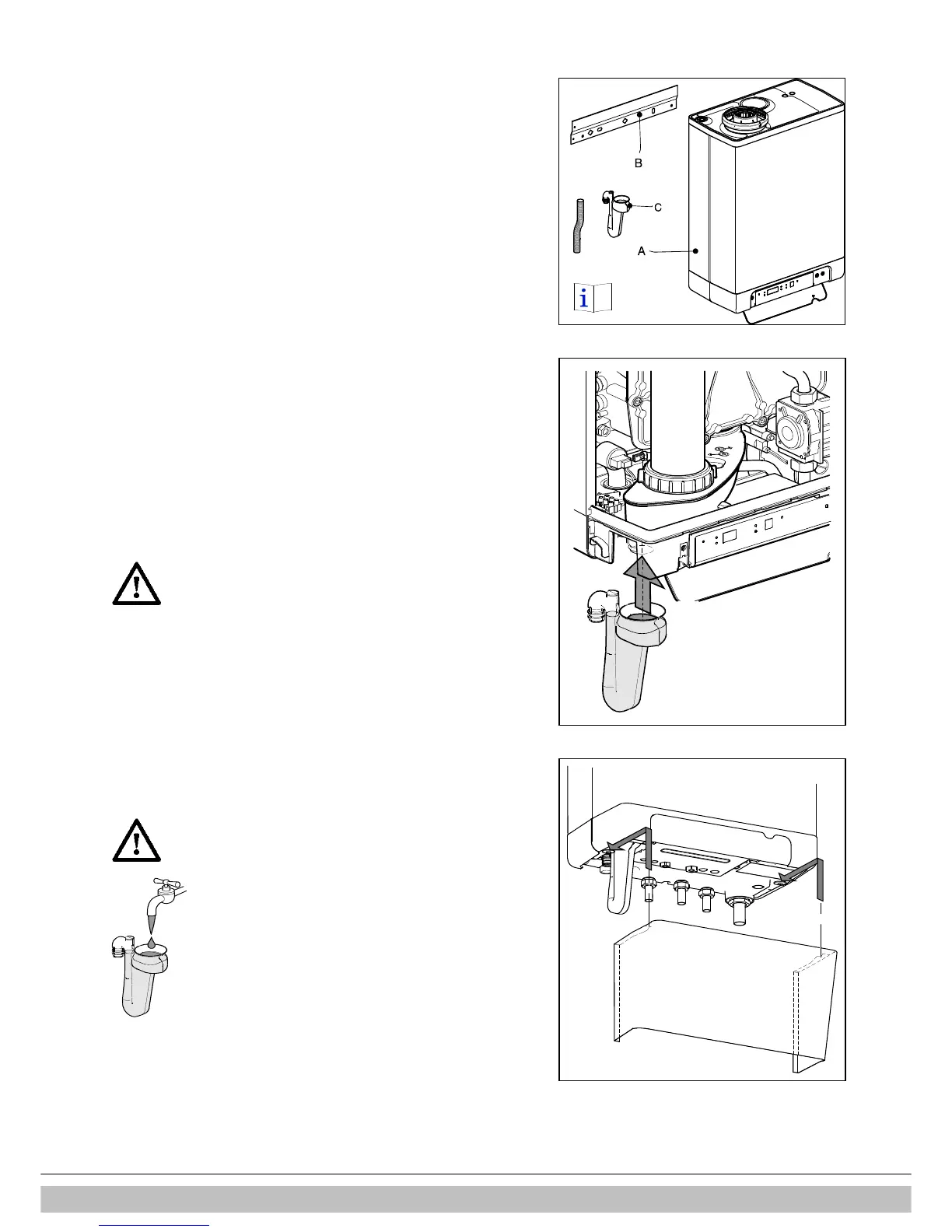
7.4 Installing the appliance
1. Unpack the appliance.
2. Check the contents of the packaging. It consists of:
• Appliance (A)
• Wall mounting strip (B)
• Condensate trap (C)
• Installation and operation instructions and warranty card
• Templates for either wall or jig mounting
3. Check the appliance for possible damage: report damage immediately to the
supplier.
4. Decide either to use the wall mounting strip (supplied) or wall mounting jig.
5. The templates show the positions for the horizontal flue. Drill the exit holes, being
sure to prevent dust or debris from entering the boiler or pipe-work.
6. If the wall mounting strip is secured to the wall then slide the boiler down until
latched.
7. If the jig is fixed securely to the wall then it is possible to fit the pipe connections
prior to hanging the boiler. Pipe connections are (from right to left) as follows for
both methods: PRV 15 mm – CH flow 22mm – DHW 15 mm – Gas 22 mm – Cold
main 15 mm – Return 22 mm.
IMPORTANT. The gas supply should be minimum 22mm up to gas isolation
valve on boiler.
It is the installers responsibility to ensure sufficient gas supply.
8. Check whether the compression rings are sitting squarely in the mounting
bracket couplings.
9. Fit the appliance, sliding it downwards on the jig. Ensure at the same time that
the pipes slide into the compression fittings.
10. Tighten the compression fittings on the mounting bracket. Do not turn tightened
valves on pipes as this weakens joints within the boiler.
11. Fit the flexible tube to the condensate trap outlet.
12. Fill the condensate trap with water and slide it as far as possible upwards on to
the condensate drain connector below the appliance.
CAUTION
The Combi Compact HRE 36/40 is only to be installed
with the condensate trap( length =235 mm) included
in the boiler package.
When replacing the condensate trap make sure the
correct version is ordered (art.nr. 844787). Using an
incorrect condensate trap can lead to potentially
unsafe situations.
13. Connect the flexible tube from the condensate trap to the drain via an open
connection. The condensate discharge system must be made of plastic, no other
materials may be used. The discharge duct must have a minimum gradient of 5
– 20 mm/m. Condensate discharge via the gutter is not allowed given the risk of
frost and the possible damage to materials.
14. Fit the flue.
CAUTION
Always fill the condensate trap with water and place
it on the boiler before powering up the boiler.
Not placing or filling up the condensate trap may
cause flue gases to come into the installation room
and can lead to dangerous situations!
In order to place the condensate trap the front cover
must be pulled forward or removed entirely.
Note
It is recommended that any external condensate pipe is insulated and increased to
32mm diameter in order to prevent the condensate from freezing
.
7.4.1 Fitting the cover plate (optional)
Hang the flanged upper edge of the cover plate on the washers under the base of the
appliance and slide the cover plate as far as possible towards the rear.

 Loading...


