Intergas Heating Ltd 36
Legionella prevention
(only applicable when using
external tank and W-plan)
0 0 0 0 0 = Legionella prevention disabled.
1 = Legionella prevention weekly
2 = Legionella prevention daily
L
Set point CH (flow temperature)
during heating external DHW tank
85 85 85 85 Adjustment range 60°C to 90°C n
Keep hot temperature Eco/Comfort
mode
0 0 0 0 Adjustment range 0, 40°C to 60°C
Setting = 0 : Keep hot temperature is related to the set
value of the DHW.
n.
Delay time for responding on CH
demand
0 0 0 0 Adjustment range 0 to 15 minutes O.
Waiting time after a DHW demand
before a CH demand is answered
0 0 0 5 Adjustment range 0 to 15 minutes o
Eco days 3 3 3 3 Adjustment range 0 until 10
Setting 1 – 10 : Eco days
Setting = 0 : keep hot facility can be set by Open Therm
room thermostat
o.
Anti cycle time
(Delay time reacting on CH
demand after exceeding maximum
setting CH temp.)
5 5 5 5 Adjustment range 0 to 15 minutes P
Ref.value DHW
24 30 36 36 0 = Combi Compact HRE equipped with flow switch.
24 = Combi Compact HRE 24/18
30 = Combi Compact HRE 28/24
36 = Combi Compact HRE 36/30 and 36/40
P.
Summer mode 0 0 0 0 Not applicable
q
Heating curve coefficient 0 0 0 0 Not applicable r
10.4 Enable/disable keep hot facility by Open Therm room thermostat.
It is possible to enable and disable the keep hot facility of the boiler by using an Open Therm
room thermostat. For this the boiler needs to be set in Eco mode : ( LED on).
Also the parameter o. needs to be set to 0. In this setting the adaptive behaviour of the
boiler (see § 4.4 ) is disabled.
The Open Therm room thermostat will now enable or disable the keep hot facility
(provided that the room thermostat supports this function)
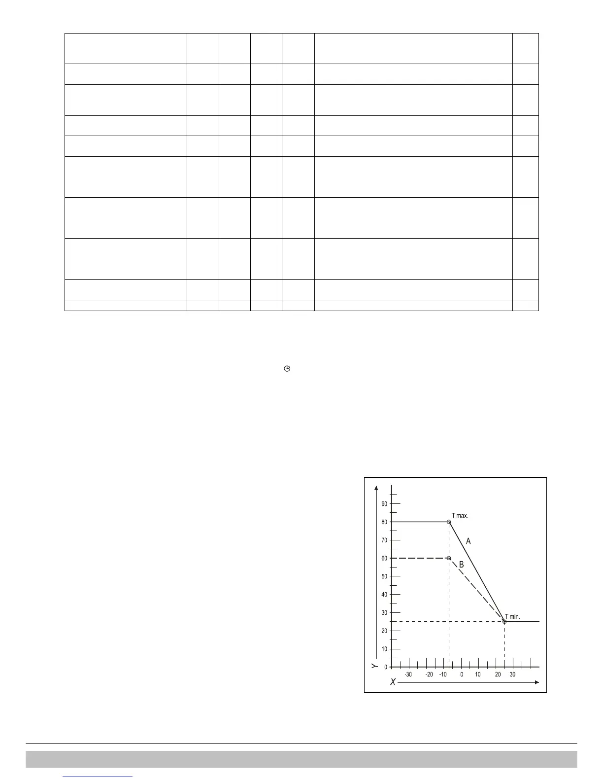
10.5 Weather– compensation adjustment
When an external sensor is connected the supply temperature is adjusted automatically
depending on the outside temperature, in accordance with the heating line set. The
maximum supply temperature (Tmax) is set via the main display. If desired, the heating
line can be changed in the parameter list. See § 10.3.
Heating line graph
X. Outside T in °C
Y. Supply T in °C
A. Factory setting
(Tmax CH = 80°C, Tmin CH = 25°C, Tmin out = -7°C, Tmax out = 25°C)
B. Example
(Tmax CH = 60°C, Tmin CH = 25°C, Tmin out= -7°C, Tmax out = 25°C)

 Loading...


