Intergas Heating Ltd
21
8.2 Connecting DHW installation
1. Flush the installation thoroughly to clean (please refer to current Standard
Codes of Practice).
2. Fit the cold and hot water pipes into the shut off valve and the elbow.
3. Existing connections must not be twisted, in order to avoid leakages.
Make sure the compression fittings are tightened thoroughly to prevent
leakage.
8.2.1 Notes
•
If the appliance is only used for the provision of hot water, the heating function
can be switched off by entering the service menu and change parameter 1.
The CH installation does not then have to be connected or filled.
•
If the appliance is taken out of operation during the winter and disconnected from
the mains supply, the DHW water must be drained in order to prevent freezing.
For this purpose the DHW connections below the appliance must be removed.
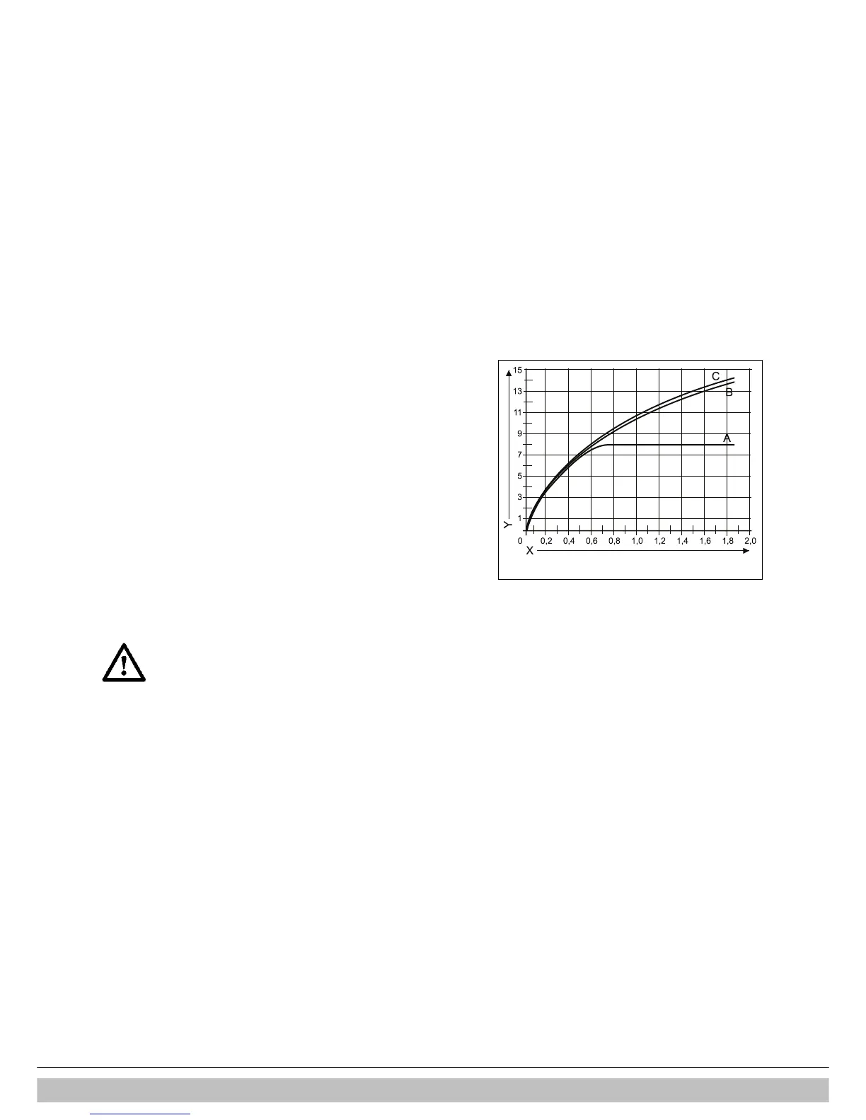
8.2.2 Flow resistance graph for appliance DHW circuit
A = Combi Compact ECO RF 24 (*)
B = Combi Compact ECO RF 30
C = Combi Compact ECO RF 36
X. Bar
Y. Litres per minute
(*) The Combi Compact ECO RF 24 is equiped with a flow restrictor of 8 litres.
When a DHW flow above 8 liters is required this flow restrictor has te be removed.
8.2.3 Minimum mains water pressure
A minimum of 0,5 bar mains cold water pressure is needed to ensure that the
DHW circuit of the Intergas ECO RF boiler is working correctly.
8.2.4 Connecting the gas supply
Important :
The boiler is intended exclusively to be installed on a gas
supply with a meter with gas pressure regulator.
When pollution in the gas is to be expected a gas filter has to
be placed in the gas pipe to the boiler.
1. Fit the gas pipe into the gas valve and tighten this thoroughly .
2. Make sure that the gas pipe is fixed to a rigid surface.
3. Open the main gas valve and purge the system
4. Check all connections for leakage.
 Loading...


